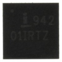
ISL94201IRZ Intersil, ISL94201IRZ Datasheet - Page 11

ISL94201IRZ
Manufacturer Part Number
ISL94201IRZ
Description
IC MULTI LI-ION AFE 24-QFN
Manufacturer
Intersil
Datasheet
1.ISL94201IRZ.pdf
(19 pages)
Specifications of ISL94201IRZ
Function
Over/Under Voltage Protection
Battery Type
Lithium-Ion (Li-Ion)
Voltage - Supply
5 V ~ 10 V
Operating Temperature
-40°C ~ 85°C
Mounting Type
Surface Mount
Package / Case
24-VFQFN Exposed Pad
Lead Free Status / RoHS Status
Lead free / RoHS Compliant
Available stocks
Company
Part Number
Manufacturer
Quantity
Price
Company:
Part Number:
ISL94201IRZ
Manufacturer:
Intersil
Quantity:
25
Part Number:
ISL94201IRZ
Manufacturer:
INTERSIL
Quantity:
20 000
Device Description
Design Theory
Instructed by the microcontroller, the ISL94201 performs cell
voltage and temperature monitoring.
System Power-Up/Power-Down
The ISL94201 powers up when the voltages on V
V
At this time, the ISL94201 wakes up and turns on the RGO
output.
RGO provides a regulated 3.3VDC ±10% voltage at pin
RGO. It does this by using a control voltage on the RGC pin
to drive an external NPN transistor (see Figure 2.) The
transistor should have a beta of at least 70 to provide ample
current to the device and external circuits and should have a
V
emitter of the NPN transistor is monitored and regulated to
3.3V by the control signal RGC. RGO also powers most of
the ISL94201internal circuits. A 500Ω resistor is
recommended in the collector of the NPN transistor to
minimize initial current surge when the regulator turns on.
Once powered up, the device remains in a wake up state
until put to sleep by the microcontroller (typically when the
cells drop too low in voltage) or until the V
V
CELL2
CE
CELL3
of greater than 30V (preferably 50V). The voltage at the
, V
or VCC voltages drop below their POR threshold.
CELL3
and VCC all exceed their POR threshold.
VCELL7
VCELL6
VCELL5
VCELL4
VCELL3
VCELL2
VCELL1
VSS
7 CELLS
11
CELL1
FIGURE 1. BATTERY CONNECTION OPTIONS
Note: Multiple cells can be connected in parallel
, V
CELL1
CELL2
VCELL7
VCELL6
VCELL5
VCELL4
VCELL3
VCELL2
VCELL1
VSS
6 CELLS
,
,
ISL94201
Battery Connection
The ISL94201supports packs of 5 to 7 series connected
Li-ion cells. Connection guidelines for each cell combination
are shown in Figure 1.
WKUP Pin Operation
There are two ways to design a wake up of the ISL94201. In
an active LOW connection (WKPOL = “0” - default), the
device wakes up when a charger is connected to the pack.
This pulls the WKUP pin low when compared to a reference
based on the V
(WKPOL = ‘1’) the device wakes up when the WKUP pin is
pulled high by a connection through an external switch.
FIGURE 2. VOLTAGE REGULATOR CIRCUITS
VCELL7
VCELL6
VCELL5
VCELL4
VCELL3
VCELL2
VCELL1
VSS
5 CELLS
CELL1
voltage. In an active HIGH connection
VCC
VSS
RGC
RGO
VCELL7
VCELL6
VCELL5
VCELL4
VCELL3
VCELL2
VCELL1
VSS
4 CELLS
500
3.3V
GND
July 3, 2008
FN6719.0


