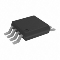
ADP2291ARMZ-R7 Analog Devices Inc, ADP2291ARMZ-R7 Datasheet - Page 10

ADP2291ARMZ-R7
Manufacturer Part Number
ADP2291ARMZ-R7
Description
IC CHARGER LI-ION 4.2V 8MSOP
Manufacturer
Analog Devices Inc
Datasheet
1.ADP2291ARMZ-R7.pdf
(20 pages)
Specifications of ADP2291ARMZ-R7
Battery Type
Lithium-Ion (Li-Ion)
Function
Charge Management
Voltage - Supply
4.5 V ~ 12 V
Operating Temperature
-40°C ~ 85°C
Mounting Type
Surface Mount
Package / Case
8-TSSOP, 8-MSOP (0.118", 3.00mm Width)
Input Voltage
12V
Battery Charge Voltage
4.2V
Charge Current Max
1.5A
Battery Ic Case Style
MSOP
No. Of Pins
8
No. Of Series Cells
1
Lead Free Status / RoHS Status
Lead free / RoHS Compliant
For Use With
ADP2291-EVAL - BOARD EVAL FOR ADP2291LI
Lead Free Status / RoHS Status
Lead free / RoHS Compliant, Lead free / RoHS Compliant
Other names
ADP2291ARMZ-R7
ADP2291ARMZ-R7TR
ADP2291ARMZ-R7TR
ADP2291
THEORY OF OPERATION
The ADP2291 is intended to charge a single-cell, lithium battery
from a supply voltage or wall adapter providing 4.5 V to 12 V.
The charge controller adjusts the base current of an external
PNP transistor to optimize current and voltage applied to the
battery during charging. A low value resistor placed in series
with the battery charging current provides current measure-
ment for the ADP2291.
To ensure safety and long battery lifetime, the ADP2291 charges
the battery using a simple step-by-step cycle, as shown in Figure 26.
The normal charge cycle begins by measuring the battery
voltage to determine charge level. If the battery is deeply dis-
charged, then low current precharge is initiated. Once precharge
is complete, normal fast charge at the maximum current (denoted
as I
varying the sense resistor value or by varying the voltage at the
adjust pin. As the battery approaches full capacity, the charging
current is reduced until the end-of-charge condition is reached.
Batteries that are not deeply discharged skip the precharge
mode and immediately begin fast charging. Each of these
modes and associated fault conditions is discussed in detail.
PRECHARGE MODE
For deeply discharged cells, the ADP2291 charges at a reduced
rate when the battery voltage V
I
ADJ pin voltage is 1.5 V. For ADJ pin voltages in between 3 V
and 1.5 V, the charge current can be interpolated. If the battery
voltage does not increase past 2.8 V before the precharge timer
elapses (typically 30 minutes), a battery fault is assumed and the
ADP2291 shuts down and does not restart until the input voltage
is cycled off and then back on. Note that in this mode, shutdown
commands are ignored.
END-OF-CHARGE MODE
Once the voltage loop reduces the charge current to 1/10 of its
nominal value, I
detects the end-of-charge (EOC) state, and the charge status
indicator becomes high impedance.
Low level charging continues until the timer terminates the
charge (nominally 30 minutes).
SHUTDOWN MODE
When the ADJ input is pulled below 0.4 V, the ADP2291 is put
into shutdown mode. When in this mode, the charger is dis-
abled; the current drawn from the battery falls to less than
1 µA; and the current drawn from IN falls to 0.7 mA.
When the charger is re-enabled, the charger returns to the start
state but quickly sequences through the states until the proper
charge mode is reached.
MAX
MAX
/10 when the ADJ pin voltage is 3 V and I
) begins. This maximum current can be adjusted by
MAX
(irrespective of the ADJ voltage), the ADP2291
BAT
< 2.8 V. This reduced rate is
MAX
/5 when the
Rev. A | Page 10 of 20
CHARGE RESTART
Once the charge is complete in the end-of-charge or timeout
mode, the ADP2291 continually monitors the cell voltage and
charge current. When the cell voltage falls by 100 mV or the
charge current increases beyond the EOC hysteresis, the ADP2291
initiates another charge cycle to keep the cell fully charged. See
Figure 26.
PROGRAMMABLE TIMER
The on-chip timer, controlled by an external capacitor CTIMER,
determines the timeout intervals of the various charger modes.
For example, a CTIMER value of 0.1 µF results in a precharge
timeout interval of 30 minutes, a fast charge timeout of 3 hours,
and an end-of-charge timeout of 30 minutes. The ratio between
precharge and end-of-charge to fast charge timeout is always
1/6. All these time intervals are proportional to the CTIMER
capacitor value, allowing them to be adjusted over a wide range.
Connecting the TIMER pin to ground disables the timer.
CHARGE STATUS INDICATOR
The ADP2291 contains a charge status output, CHG , that sinks
current when the ADP2291 is charging the battery. This output
can be used as a visual signal by connecting it to an LED, or it
can be used to generate a logic-level charge status signal by
connecting a resistor between CHG and logic high.
AUTOMATIC REVERSE ISOLATION
When the voltage on the BAT pin is higher than the voltage on
IN, the ADP2291 automatically connects the base of the pass
device to BAT. This removes the necessity of having an external
diode between the pass device and battery, further reducing the
charger’s footprint and component count.
OVERSHOOT PROTECTION
In the event of a battery disconnect during charging, a voltage
overshoot condition on BAT could occur. The ADP2291
includes an overshoot protection circuit that activates when
V
components.
POWER SUPPLY CHECKS
To ensure proper operation, the ADP2291 checks the absolute
voltage level of the input supply and the supply voltage relative
to the battery. When the supply IN is below 3.8 V, the chip is
internally powered down and does not respond to external
control. In this power-down mode, the device draws less than
1 µA from the battery. The V
if the supply voltage is less than 165 mV above the battery
voltage, ensuring that charging occurs only if the supply voltage
is sufficient.
BAT
rises to 5 V and sinks up to 1.5 A to protect the external
IN
good comparator halts operation


