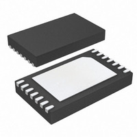
DS2777G+ Maxim Integrated Products, DS2777G+ Datasheet - Page 41

DS2777G+
Manufacturer Part Number
DS2777G+
Description
IC FUEL GAUGE LI+ 2CELL 14-TDFN
Manufacturer
Maxim Integrated Products
Datasheet
1.DS2775G.pdf
(46 pages)
Specifications of DS2777G+
Function
Fuel, Gas Gauge/Monitor
Battery Type
Lithium-Ion (Li-Ion), Lithium-Polymer (Li-Pol)
Voltage - Supply
4 V ~ 9.2 V
Operating Temperature
-20°C ~ 70°C
Mounting Type
Surface Mount
Package / Case
14-TDFN
Lead Free Status / RoHS Status
Lead free / RoHS Compliant
A write time slot is initiated when the bus master pulls
the 1-Wire bus from a logic-high (inactive) level to a
logic-low level. There are two types of write time slots:
write-one and write-zero. All write time slots must be
t
t
1-Wire bus line between t
after the line falls. If the line is high when sampled, a
write-one occurs. If the line is low when sampled, a
write-zero occurs. Figure 30 illustrates the sample win-
dow. For the bus master to generate a write-one time
slot, the bus line must be pulled low and then released,
allowing the line to be pulled high less than t
the start of the write time slot. For the host to generate a
write-zero time slot, the bus line must be pulled low and
held low for the duration of the write time slot.
A read time slot is initiated when the bus master pulls the
1-Wire bus line from a logic-high level to a logic-low
level. The bus master must keep the bus line low for at
least 1µs and then release it to allow the DS2775/
DS2776 to present valid data. The bus master can then
sample the data t
By the end of the read time slot, the DS2775/DS2776
release the bus line and allow it to be pulled high by the
external pullup resistor. All read time slots must be t
in duration with a 1µs minimum recovery time, t
between cycles. See Figure 30 and the timing specifica-
tions in the Electrical Characteristics: 1-Wire Interface,
Standard/Overdrive tables for more information.
The 2-wire bus system supports operation as a slave-
only device in a single or multislave and single or multi-
master system. Up to 128 slave devices can share the
bus by uniquely setting the 7-bit slave address. The
2-wire interface consists of a serial data line (SDA) and
serial clock line (SCL). SDA and SCL provide bidirec-
tional communication between the DS2777/DS2778
slave device and a master device at speeds up to
400kHz. The DS2777/DS2778’s SDA pin operates bidi-
rectionally, that is, when the DS2777/DS2778 receive
data, SDA operates as an input, and when the
DS2777/DS2778 return data, SDA operates as an open-
drain output with the host system providing a resistive
pullup. The DS2777/DS2778 always operate as a slave
device, receiving and transmitting data under the con-
SLOT
REC
, between cycles. The DS2775/DS2776 sample the
in duration with a 1µs minimum recovery time,
Protector and Optional SHA-1 Authentication
2-Cell, Stand-Alone, Li+ Fuel-Gauge IC with
RDV
______________________________________________________________________________________
from the start of the read time slot.
2-Wire Bus System
LOW1_MAX
Write Time Slots
Read Time Slots
and t
LOW0_MIN
RDV
SLOT
REC
after
,
trol of a master device. The master initiates all transac-
tions on the bus and generates the SCL signal as well
as the START and STOP bits which begin and end
each transaction.
One data bit is transferred during each SCL clock cycle
with the cycle defined by SCL transitioning low-to-high
and then high-to-low. The SDA logic level must remain
stable during the high period of the SCL clock pulse.
Any change in SDA when SCL is high is interpreted as
a START (S) or STOP (P) control signal.
The bus is defined to be idle, or not busy, when no
master device has control. Both SDA and SCL remain
high when the bus is idle. The STOP condition is the
proper method to return the bus to the idle state.
The master initiates transactions with a START condi-
tion by forcing a high-to-low transition on SDA while
SCL is high. The master terminates a transaction with a
STOP condition, a low-to-high transition on SDA while
SCL is high. A repeated START condition (Sr) can be
used in place of a STOP then START sequence to ter-
minate one transaction and begin another without
returning the bus to the idle state. In multimaster sys-
tems, a repeated START allows the master to retain
control of the bus. The START and STOP conditions are
the only bus activities in which the SDA transitions
when SCL is high.
Each byte of a data transfer is acknowledged with an
acknowledge bit (A) or a not acknowledge bit (N). Both
the master and the DS2777/DS2778 slave generate
acknowledge bits. To generate an acknowledge, the
receiving device must pull SDA low before the rising
edge of the acknowledge-related clock pulse (9th
pulse) and keep it low until SCL returns low. To gener-
ate a not acknowledge (also called NACK), the receiver
releases SDA before the rising edge of the acknowl-
edge-related clock pulse and leaves SDA high until
SCL returns low. Monitoring the acknowledge bits
allows for detection of unsuccessful data transfers. An
unsuccessful data transfer can occur if a receiving
device is busy or if a system fault has occurred. In the
event of an unsuccessful data transfer, the bus master
should reattempt communication.
START and STOP Conditions
Acknowledge Bits
Bit Transfer
Bus Idle
41


