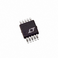
LTC1733EMSE#TR Linear Technology, LTC1733EMSE#TR Datasheet - Page 8

LTC1733EMSE#TR
Manufacturer Part Number
LTC1733EMSE#TR
Description
IC CTRLR BATT CHRG LI-ION 10MSOP
Manufacturer
Linear Technology
Datasheet
1.LTC1733EMSE.pdf
(16 pages)
Specifications of LTC1733EMSE#TR
Function
Charge Management
Battery Type
Lithium-Ion (Li-Ion)
Voltage - Supply
4.5 V ~ 6.5 V
Operating Temperature
-40°C ~ 85°C
Mounting Type
Surface Mount
Package / Case
10-TFSOP, 10-MSOP (0.118", 3.00mm Width) Exposed Pad
Lead Free Status / RoHS Status
Contains lead / RoHS non-compliant
Available stocks
Company
Part Number
Manufacturer
Quantity
Price
OPERATIO
LTC1733
The LTC1733 is a linear battery charger designed primarily
for charging single cell lithium-ion batteries. Featuring an
internal P-channel power MOSFET, the charger uses a
constant-current/constant-voltage charge algorithm with
programmable current and a programmable timer for
charge termination. Charge current can be programmed
up to 1.5A with a final float voltage accuracy of 1%. No
blocking diode or sense resistor is required thus dropping
the external component count to three for the basic
charger circuit. The CHRG, ACPR, and FAULT open-drain
status outputs provide information regarding the status of
the LTC1733 at all times. An NTC thermistor input
provides the option of charge qualification using battery
temperature.
An internal thermal limit reduces the programmed charge
current if the die temperature attempts to rise above a
preset value of approximately 105 C. This feature protects
the LTC1733 from excessive temperature, and allows the
user to push the limits of the power handling capability of
a given circuit board without risk of damaging the LTC1733
or the external components. Another benefit of the LTC1733
thermal limit is that charge current can be set according to
typical, not worst-case, ambient temperatures for a given
application with the assurance that the charger will auto-
matically reduce the current in worst-case conditions.
The charge cycle begins when the voltage at the V
rises above the UVLO level and a program resistor is
connected from the PROG pin to ground. At the beginning
of the charge cycle, if the battery voltage is below 2.48V,
the charger goes into trickle charge mode to bring the cell
voltage up to a safe level for charging. The charger goes
8
U
CC
pin
into the fast charge constant-current mode once the
voltage on the BAT pin rises above 2.48V. In constant-
current mode, the charge current is set by R
When the battery approaches the final float voltage, the
charge current begins to decrease as the LTC1733 switches
to constant-voltage mode. When the current drops to 10%
of the full-scale charge current, an internal comparator
latches off the MOSFET at the CHRG pin and connects a
weak current source to ground to indicate a near end-of-
charge (C/10) condition. The C/10 latch can be cleared by
momentarily pulling the PROG pin above the 2.15V
shutdown threshold, or momentarily removing and reap-
plying V
An external capacitor on the TIMER pin sets the total
charge time. When this time elapses the charge cycle
terminates and the CHRG pin assumes a high impedance
state. To restart the charge cycle, simply remove the input
voltage and reapply it, or force the PROG pin above the
2.15V shutdown threshold (note: simply floating the PROG
pin will not restart the charging cycle.
For lithium-ion and similar batteries that require accurate
final float potential, the internal reference, voltage ampli-
fier and the resistor divider provide regulation with 1%
(max) accuracy.
When the input voltage is not present, the charger goes
into a sleep mode, dropping battery drain current, I
less than 5 A. This greatly reduces the current drain on the
battery and increases the standby time. The charger can be
shut down (I
2.15V.
CC
.
CC
= 0.9mA) by forcing the PROG pin above
PROG
sn1733 1733fs
.
BAT
, to


