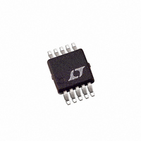
LTC1733EMSE#TR Linear Technology, LTC1733EMSE#TR Datasheet - Page 9

LTC1733EMSE#TR
Manufacturer Part Number
LTC1733EMSE#TR
Description
IC CTRLR BATT CHRG LI-ION 10MSOP
Manufacturer
Linear Technology
Datasheet
1.LTC1733EMSE.pdf
(16 pages)
Specifications of LTC1733EMSE#TR
Function
Charge Management
Battery Type
Lithium-Ion (Li-Ion)
Voltage - Supply
4.5 V ~ 6.5 V
Operating Temperature
-40°C ~ 85°C
Mounting Type
Surface Mount
Package / Case
10-TFSOP, 10-MSOP (0.118", 3.00mm Width) Exposed Pad
Lead Free Status / RoHS Status
Contains lead / RoHS non-compliant
Available stocks
Company
Part Number
Manufacturer
Quantity
Price
APPLICATIO S I FOR ATIO
Undervoltage Lockout (UVLO)
An internal undervoltage lockout circuit monitors the input
voltage and keeps the charger in shutdown mode until V
rises above the undervoltage lockout threshold. The UVLO
circuit has a built-in hysteresis of 150mV. Furthermore, to
protect against reverse current in the power MOSFET, the
UVLO circuit keeps the charger in shutdown mode if V
falls to within 30mV of the battery voltage. If the UVLO
comparator is tripped, the charger will not come out of
shutdown until V
Trickle Charge and Defective Battery Detection
At the beginning of a charge cycle, if the battery voltage is
low (below 2.48V) the charger goes into trickle charge
reducing the charge current to 10% of the full-scale
current. If the low battery voltage persists for one quarter
of the total charge time, the battery is assumed to be
defective, the charge cycle is terminated, the CHRG pin
output assumes a high impedance state, and the FAULT
pin latches low. The fault can be cleared by toggling V
temporarily forcing the PROG pin above 2.15V, or tempo-
rarily forcing the BAT pin voltage above 2.48V.
Shutdown
The LTC1733 can be shutdown (I
the PROG pin above the 2.15V shutdown threshold volt-
age. In shutdown the internal linear regulator is turned off,
and the internal timer is reset.
Recharge
The LTC1733 has the ability to recharge a battery
assuming that the battery voltage has been charged above
4.05V (SEL = 5V) or 3.95V (SEL = 0V). Once above these
thresholds, a new charge cycle will begin if the battery
voltage drops below 4V (SEL = 5V) or 3.9V (SEL = 0V) due
to either a load on the battery or self-discharge. The
recharge circuit integrates the BAT pin voltage for a few
milliseconds to prevent a transient from restarting the
charge cycle.
If the battery voltage remains below 2.48V during trickle
charge for 1/4 of the programmed time, the battery may be
defective and the charge cycle will end. In addition, the
CC
rises 60mV above the battery voltage.
U
U
CC
W
= 0.9mA) by pulling
U
CC
CC
CC
,
recharge comparator is disabled and a new charge cycle
will not begin unless the input voltage is toggled, the PROG
pin is pulled above the 2.15V shutdown threshold, or the
BAT pin is pulled above the 2.48V trickle charge threshold.
Programming Charge Current
The formula for the battery charge current (see Figure 1)
is:
where R
ground. Under trickle charge conditions, this current is
reduced to 10% of the full-scale value.
For example, if 500mA charge current is required,
calculate:
For best stability over temperature and time, 1% metal-
film resistors are recommended.
If the charger is in constant-temperature or constant-
voltage mode, the battery current can be monitored by
measuring the PROG pin voltage as follows:
Programming the Timer
The programmable timer is used to terminate the charge
cycle. The timer duration is programmed by an external
capacitor at the TIMER pin. The total charge time is:
The timer starts when an input voltage greater than the
undervoltage lockout threshold level is applied and the
program resistor is connected to ground. After a time-out
occurs, the charge current stops, and the CHRG output
assumes a high impedance state to indicate that the
charging has stopped. Connecting the TIMER pin to ground
disables the timer function.
I
R
R
I
Time (Hours) = (3 Hours) • (C
C
CHG
CHG
TIMER
PROG
PROG
= (V
= (I
= (1.5V / R
PROG
= 1500/I
= 1500/0.5A = 3k
= 0.1 F • Time (Hours)/3 (Hours)
PROG
PROG
is the total resistance from the PROG pin to
) • 1000
/ R
CHG
PROG
PROG
) • 1000 or
) • 1000
TIMER
/ 0.1 F) or
LTC1733
sn1733 1733fs
9


