ISL6251HAZ-T Intersil, ISL6251HAZ-T Datasheet - Page 15
ISL6251HAZ-T
Manufacturer Part Number
ISL6251HAZ-T
Description
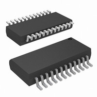
IC BATTERY CHARGER CTRLR 24-QSOP
Manufacturer
Intersil
Datasheet
1.ISL6251HRZ.pdf
(20 pages)
Specifications of ISL6251HAZ-T
Function
Charge Management
Battery Type
Li-Ion, Li-Pol, NiMH
Voltage - Supply
7 V ~ 25 V
Operating Temperature
-10°C ~ 100°C
Mounting Type
Surface Mount
Package / Case
24-QSOP
Lead Free Status / RoHS Status
Lead free / RoHS Compliant


600kHz operation with low core loss. The core must be large
enough not to saturate at the peak inductor current I
Output Capacitor Selection
The output capacitor in parallel with the battery is used to
absorb the high frequency switching ripple current and
smooth the output voltage. The RMS value of the output
ripple current I
where the duty cycle D is the ratio of the output voltage
(battery voltage) over the input voltage for continuous
conduction mode which is typical operation for the battery
charger. During the battery charge period, the output voltage
varies from its initial battery voltage to the rated battery
voltage. So, the duty cycle change can be in the range of
between 0.53 and 0.88 for the minimum battery voltage of
10V (2.5V/Cell) and the maximum battery voltage of 16.8V.
For V
f
10F ceramic capacitor is a good choice to absorb this
current and also has very small size. The tantalum capacitor
has a known failure mechanism when subjected to high
surge current.
EMI considerations usually make it desirable to minimize
ripple current in the battery leads. Beads may be added in
series with the battery pack to increase the battery
impedance at 300kHz switching frequency. Switching ripple
current splits between the battery and the output capacitor
depending on the ESR of the output capacitor and battery
impedance. If the ESR of the output capacitor is 10m Ω and
battery impedance is raised to 2 Ω with a bead, then only
0.5% of the ripple current will flow in the battery.
MOSFET Selection
The Notebook battery charger synchronous buck converter
has the input voltage from the AC adapter output. The
maximum AC adapter output voltage does not exceed 25V.
Therefore, 30V logic MOSFET should be used.
The high side MOSFET must be able to dissipate the
conduction losses plus the switching losses. For the battery
charger application, the input voltage of the synchronous
buck converter is equal to the AC adapter output voltage,
which is relatively constant. The maximum efficiency is
achieved by selecting a high side MOSFET that has the
conduction losses equal to the switching losses. Ensure that
ISL6251, ISL6251A LGATE gate driver can supply sufficient
gate current to prevent it from conduction, which is due to
the injected current into the drain-to-source parasitic
capacitor (Miller capacitor C
rising rate at phase node at the time instant of the high-side
I
I
s
RMS
Peak
= 300kHz, the maximum RMS current is 0.19A. A typical
IN,MAX
=
=
V
I
BAT
12
IN
,
MAX
f L
,
MAX
= 19V, VBAT = 16.8V, L = 10µH, and
rms
s
D
+
is given by:
(
1
1
2
−
Δ
D
I
)
L
gd
15
), and caused by the voltage
ISL6251, ISL6251A
Peak
:
MOSFET turning on; otherwise, cross-conduction problems
may occur. Reasonably slowing turn-on speed of the
high-side MOSFET by connecting a resistor between the
BOOT pin and gate drive supply source, and the high sink
current capability of the low-side MOSFET gate driver help
reduce the possibility of cross-conduction.
For the high-side MOSFET, the worst-case conduction
losses occur at the minimum input voltage:
The optimum efficiency occurs when the switching losses
equal the conduction losses. However, it is difficult to
calculate the switching losses in the high-side MOSFET
since it must allow for difficult-to-quantify factors that
influence the turn-on and turn-off times. These factors
include the MOSFET internal gate resistance, gate charge,
threshold voltage, stray inductance, pull-up and pull-down
resistance of the gate driver. The following switching loss
calculation provides a rough estimate.
Where Q
charge of the body-diode in low side MOSFET, I
valley current, I
I
respectively.
To achieve low switching losses, it requires low drain-to-gate
charge Q
the higher the on-resistance. Therefore, there is a trade-off
between the on-resistance and drain-to-gate charge. Good
MOSFET selection is based on the Figure of Merit (FOM),
which is a product of the total gate charge and
on-resistance. Usually, the smaller the value of FOM, the
higher the efficiency for the same application.
For the low-side MOSFET, the worst-case power dissipation
occurs at minimum battery voltage and maximum input
voltage:
Choose a low-side MOSFET that has the lowest possible
on-resistance with a moderate-sized package like the SO-8
and is reasonably priced. The switching losses are not an
issue for the low side MOSFET because it operates at
zero-voltage-switching.
Choose a Schottky diode in parallel with low-side MOSFET
Q2 with a forward voltage drop low enough to prevent the
low-side MOSFET Q2 body-diode from turning on during the
dead time. This also reduces the power loss in the high-side
MOSFET associated with the reverse recovery of the
low-side MOSFET Q2 body diode.
P
P
P
g
Q
,
Q
Q
source
, 1
, 1
2
Switching
Conduction
=
⎛
⎜
⎜
⎝
1
gd
are the peak gate-drive source/sink current of Q1,
gd
−
: drain-to-gate charge, Q
V
. Generally, the lower the drain-to-gate charge,
V
=
OUT
IN
=
1
2
LP:
V
V
⎞
⎟
⎟
⎠
V
IN
OUT
I
Inductor peak current, I
IN
BAT
2
I
LV
R
I
f
s
BAT
2
DSON
I
, g
Q
R
source
gd
DSON
+
rr
1
2
: total reverse recovery
V
IN
I
LP
g,sink
f
s
I
LV
, g
and
Q
sin
gd
: inductor
May 10, 2006
k
FN9202.2
+
Q
rr
V
IN
f
s
Related parts for ISL6251HAZ-T
Image
Part Number
Description
Manufacturer
Datasheet
Request
R

Part Number:
Description:
Low Cost Multi-Chemistry Battery Charger Controller
Manufacturer:
INTERSIL [Intersil Corporation]
Datasheet:

Part Number:
Description:
Intersil Corporation [CMOS Serial Controller Interface]
Manufacturer:
Intersil Corporation
Datasheet:
Part Number:
Description:
Manufacturer:
Intersil Corporation
Datasheet:
Part Number:
Description:
357-036-542-201 CARDEDGE 36POS DL .156 BLK LOPRO
Manufacturer:
Intersil Corporation
Datasheet:
Part Number:
Description:
1024-Word x 4-Bit LSI Static RAM
Manufacturer:
Intersil Corporation
Datasheet:
Part Number:
Description:
General Purpose NPN Transistor Arrays FN341.4
Manufacturer:
Intersil Corporation
Datasheet:
Part Number:
Description:
CMOS 16-Bit Microprocessor
Manufacturer:
Intersil Corporation
Datasheet:
Part Number:
Description:
Manufacturer:
Intersil Corporation
Datasheet:
Part Number:
Description:
Manufacturer:
Intersil Corporation
Datasheet:
Part Number:
Description:
Manufacturer:
Intersil Corporation
Datasheet:
Part Number:
Description:
Manufacturer:
Intersil Corporation
Datasheet:
Part Number:
Description:
CMOS 6-Bit Latch and Decoder Memory Interfaces
Manufacturer:
Intersil Corporation
Datasheet:
Part Number:
Description:
CA3046General Purpose NPN Transistor Arrays
Manufacturer:
Intersil Corporation
Datasheet:
Part Number:
Description:
Manufacturer:
Intersil Corporation
Datasheet:
Part Number:
Description:
TR909 DLC/FLC SLIC with Low Power Standby
Manufacturer:
Intersil Corporation
Datasheet: