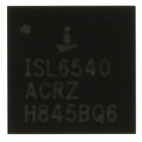
ISL6252HRZ Intersil, ISL6252HRZ Datasheet - Page 14

ISL6252HRZ
Manufacturer Part Number
ISL6252HRZ
Description
IC BATTERY CHARGER CTRLR 28-QFN
Manufacturer
Intersil
Datasheet
1.ISL6252HAZ.pdf
(25 pages)
Specifications of ISL6252HRZ
Function
Charge Management
Battery Type
Lithium-Ion (Li-Ion), Lithium-Polymer (Li-Pol)
Voltage - Supply
7 V ~ 25 V
Operating Temperature
-10°C ~ 100°C
Mounting Type
Surface Mount
Package / Case
28-VFQFN Exposed Pad
Lead Free Status / RoHS Status
Lead free / RoHS Compliant
Equation 5 shows the formula for the max full scale
CSOP-CSON voltage (in mV) for the ISL6252:
With CHLIM = 1.5V, the maximum CSOP-CSON voltage is
78mV and the minimum CSOP-CSON voltage is 72mV.
When ISL6252A is in charge current limiting mode, the
maximum charge current is the maximum CSOP-CSON
voltage divided by the minimum sense resistor. This can be
calculated for ISL6252A with Equation 7:
I
Maximum charge current can be calculated for ISL6252 with
Equation 8:
I
With CHLIM = 0.7V and R
I
Setting the Input Current Limit
The total input current from an AC adapter, or other DC
source, is a function of the system supply current and the
battery-charging current. The input current regulator limits
the input current by reducing the charging current, when the
input current exceeds the input current limit set point.
System current normally fluctuates as portions of the system
are powered up or down. Without input current regulation,
the source must be able to supply the maximum system
current and the maximum charger input current
simultaneously. By using the input current limiter, the current
capability of the AC adapter can be lowered, reducing
system cost.
The ISL6252 limits the battery charge current when the input
current-limit threshold is exceeded, ensuring the battery
charger does not load down the AC adapter voltage. This
constant input current regulation allows the adapter to fully
power the system and prevent the AC adapter from
overloading and crashing the system bus.
An internal amplifier gm3 compares the voltage between
CSIP and CSIN to the input current limit threshold voltage
set by ACLIM. Connect ACLIM to REF, Float and GND for
the full-scale input current limit threshold voltage of 100mV,
75mV and 50mV, respectively, or use a resistor divider from
VREF to ground to set the input current limit as Equation 10:
I
I
I
MAX CSOP CSON
CHG MAX
CHG MIN
CHG MAX
CHG MIN
CHG MAX
MIN CSOP CSON
CHG MIN
,
,
,
,
,
(
,
(
=
=
=
=
=
=
–
(
(
–
(
(
(
(
CHLIM 49.72 2.4
CHLIM 50 5
1.5V 49.72 2.4
CHLIM 50.28
CHLIM 50
1.5V 50.28
ISL6252
ISL6252
ISL6252A
•
•
ISL6252A
)
)
•
•
•
•
=
=
CHLIM 50 5
CHLIM 50
–
+
–
+
1
5
2.4
–
) R
= 0.02Ω, 1%:
+
) R
⁄
14
⁄
2.4
) 0.0202
) 0.0198
⁄
1MAX
⁄
•
1MIN
•
) R
) R
⁄
⁄
1MAX
–
+
1MIN
5
=
=
3573mA
3930mA
ISL6252, ISL6252A
(EQ. 7)
(EQ. 8)
(EQ. 6)
(EQ. 9)
An external resistor divider from VREF sets the voltage at
ACLIM according to Equation 11:
where R
ACLIM.
To minimize accuracy loss due to interaction with ACLIM's
internal resistor divider, ensure the AC resistance looking
back into the resistor divider is less than 25k.
When choosing the current sense resistor, note that the
voltage drop across this resistor causes further power
dissipation, reducing efficiency. The AC adapter current
sense accuracy is very important. Use a 1% tolerance
current-sense resistor. The highest accuracy of ±3% is
achieved with 100mV current-sense threshold voltage for
ACLIM = VREF, but it has the highest power dissipation. For
example, it has 400mW power dissipation for rated 4A AC
adapter and 1Ω sensing resistor may have to be used. ±4%
and ±6% accuracy can be achieved with 75mV and 50mV
current-sense threshold voltage for ACLIM = Floating and
ACLIM = GND, respectively.
A low pass filter is suggested to eliminate the switching
noise. Connect the resistor to CSIN pin instead of CSIP pin
because CSIN pin has lower bias current and less influence
on the current-sense accuracy.
AC Adapter Detection
Connect the AC adapter voltage through a resistor divider to
ACSET to detect when AC power is available, as shown in
Figure 2. ACPRN is an open-drain output and is high when
ACSET is less than V
above V
and Equation 13:
where:
• I
• V
The hysteresis is I
3.4µA (typ) and 4.4µA (max).
V
V
V
I
th rise
th fall
ACLIM
INPUT
hys
,
,
ACSET
is the ACSET input bias current hysteresis, and
=
=
th,fall
bot_ACLIM
=
=
⎛
⎜
⎝
⎛
⎜
⎝
VREF
R
------ -
R
------ -
R
= 1.24V (min), 1.26V (typ) and 1.28V (max).
R
------ -
R
1
8
9
2
8
9
. V
+
⋅
+
⎛
⎝
1
th,rise
---------------- - V
VREF
1
⎞
⎟
⎠
0.05
⋅
⎞
⎟
⎠
⋅
⎛
⎜
⎝
hys
⋅
----------------------------------------------------------------------------------------------------------------------- -
R
V
and R
V
ACSET
top ACLIM
ACSET
R
th,rise
and V
⋅
8
,
, where I
ACLIM
top_ACLIM
, and active low when ACSET is
–
th,fall
I
hys
R
||
bot ACLIM
+
152kΩ
hys
0.05
⋅
are given by Equation 12
,
R
8
are external resistors at
⎞
⎠
= 2.2µA (min),
+
R
||
bot ACLIM
152kΩ
,
August 25, 2010
||
(EQ. 10)
(EQ. 12)
(EQ. 13)
(EQ. 11)
152kΩ
FN6498.3
⎞
⎟
⎠


