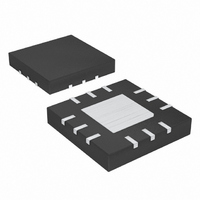
MAX1925ETC+ Maxim Integrated Products, MAX1925ETC+ Datasheet

MAX1925ETC+
Specifications of MAX1925ETC+
Related parts for MAX1925ETC+
MAX1925ETC+ Summary of contents
Page 1
... ACON CT CS THIN QFN ________________________________________________________________ Maxim Integrated Products For pricing, delivery, and ordering information, please contact Maxim/Dallas Direct! at 1-888-629-4642, or visit Maxim’s website at www.maxim-ic.com. Switch-Mode 1-Cell Li+ Chargers o Small (4mm o 4.25V to 12V Input Range (MAX1926) o Overvoltage Lockout at 6.1V (MAX1925) o ±0.75% Battery Regulation Voltage ...
Page 2
Switch-Mode 1-Cell Li+ Chargers ABSOLUTE MAXIMUM RATINGS IN, INP, ACON to GND...........................................-0.3V to +14V CHG, EXT to PGND ...................................-0. CS, BATT, EN, THRM to GND ..................................-0. GND ................................................................-0.3V to +4V EN, THRM ...
Page 3
ELECTRICAL CHARACTERISTICS (continued CHG PGND GND INP IN unless otherwise noted. Typical values are at T PARAMETER Restart Threshold Charging restarts when BATT falls to this point If BATT exceeds ...
Page 4
Switch-Mode 1-Cell Li+ Chargers ELECTRICAL CHARACTERISTICS ( CHG PGND GND INP IN unless otherwise noted. Typical values are at T PARAMETER Supply Voltage Range V INP V INP ACON Trip point ...
Page 5
ELECTRICAL CHARACTERISTICS (continued CHG PGND GND INP IN unless otherwise noted. Typical values are at T PARAMETER CHG Output High Leakage V CHG Current ACON High Leakage V ACON ACON ...
Page 6
Switch-Mode 1-Cell Li+ Chargers (Circuit of Figure 5V, V SUPPLY BATT CHARGE-CURRENT ACCURACY vs. SUPPLY VOLTAGE BATT -10 -15 - ...
Page 7
Figure 5V, V SUPPLY BATT FREQUENCY vs. BATTERY VOLTAGE 500 V = 12V IN 450 400 350 300 250 200 150 100 50 0 2.5 3.0 3.5 ...
Page 8
Switch-Mode 1-Cell Li+ Chargers PIN NAME Charge Status LED Driver. Open-drain LED driver sinks 10mA when the MAX1925/MAX1926 are charging. CHG CHG also blinks at a 0.5Hz rate during fault states (see the Timing section). High impedance when charger is ...
Page 9
D1 POWER SOURCE C3 D3 10µF LED CHG IN 4.5V FOR MAX1926 4.25V FOR MAX1925 10mA 6.1V MAX1925 ONLY OSC C2 0.1µF ACON STATE EN MACHINE AND TIMERS TEMP FAULT 353µA 49µA THRM 10kΩ REF Figure 1. Functional Diagram _______________________________________________________________________________________ ...
Page 10
Switch-Mode 1-Cell Li+ Chargers Detailed Description The MAX1925/MAX1926 switch-mode battery chargers form a complete solution for a single-cell Li+ battery. The devices include battery undervoltage/overvoltage fault protection. The MAX1925/MAX1926 use EN and THRM for shutdown, battery detection, and temperature monitor- ...
Page 11
FULL TOPOFF 4V PREQUAL1 4mA FAULT 1V t PREQUAL2 t = t/1024 PREQUAL1 Figure 3. Charging Current and Voltage Timing Diagrams linear 4mA current source (PREQUAL1). When the cell voltage exceeds 2V, the cell ...
Page 12
Switch-Mode 1-Cell Li+ Chargers and a new battery is connected during either fast-charge or full topoff modes, the charger begins with full charge current without prequalification unless the part is reset. Detect battery insertion by connecting THRM to a ther- ...
Page 13
Table 2. ACON Behavior vs. V PART V > V threshold (4.5V nom) and < 6.1V, and ACON IN V > BATT MAX1925 V > V threshold and V ACON IN (Note: This state should never occur) V ...
Page 14
Switch-Mode 1-Cell Li+ Chargers mode. To ensure stable transition from CCM to CVM choose a capacitor with the following ESR: V VHIST > × ESR SET V IHIST where V is the voltage hysteresis (15mV typ) and VHIST ...
Page 15
For the latest package outline information www.maxim-ic.com/packages.) ______________________________________________________________________________________ Switch-Mode 1-Cell Li+ Chargers Package Information PACKAGE OUTLINE 12,16,20,24L QFN THIN, 4x4x0.8 mm 21-0139 A 15 ...
Page 16
... Maxim cannot assume responsibility for use of any circuitry other than circuitry entirely embodied in a Maxim product. No circuit patent licenses are implied. Maxim reserves the right to change the circuitry and specifications without notice at any time. 16 ____________________Maxim Integrated Products, 120 San Gabriel Drive, Sunnyvale, CA 94086 408-737-7600 © 2002 Maxim Integrated Products ...


