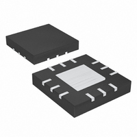
MAX1925ETC+ Maxim Integrated Products, MAX1925ETC+ Datasheet - Page 12

MAX1925ETC+
Manufacturer Part Number
MAX1925ETC+
Description
IC CHARGER LI+ 12-TQFN
Manufacturer
Maxim Integrated Products
Datasheet
1.MAX1926ETCT.pdf
(16 pages)
Specifications of MAX1925ETC+
Function
Charge Management
Battery Type
Lithium-Ion (Li-Ion)
Voltage - Supply
4.5 V ~ 12 V
Operating Temperature
-40°C ~ 85°C
Mounting Type
Surface Mount
Package / Case
12-TQFN Exposed Pad
Product
Charge Management
Operating Supply Voltage
4.25 V to 12 V
Supply Current
39 uA
Maximum Operating Temperature
+ 85 C
Minimum Operating Temperature
- 40 C
Charge Safety Timers
Yes
Mounting Style
SMD/SMT
Temperature Monitoring
Yes
Lead Free Status / RoHS Status
Lead free / RoHS Compliant
and a new battery is connected during either fast-charge
or full topoff modes, the charger begins with full charge
current without prequalification unless the part is reset.
Detect battery insertion by connecting THRM to a ther-
mistor on the battery, if a thermistor is used, or to a 10kΩ
resistor linked to a battery door mechanism.
When the battery voltage is below 4.2V, the
MAX1925/MAX1926 regulate the charging current by
controlling the peak and valley inductor currents. When
the inductor current exceeds the 158mV/R
MAX1925/MAX1926 turn the external PFET off. When
the inductor current falls below 128mV/R
MAX1925/MAX1926 turns the external PFET on, but
only if the battery voltage is below regulation. The maxi-
mum cell charging current is programmed by selecting
the external R
between BATT and CS. Select the external resistor
value using R
The accuracy of the charge current is a function of
input voltage, battery voltage, inductance, and com-
parator delay (300ns typ). Determine the charge-cur-
rent error according to the following equation:
where ∆I
the current-sense comparator delay.
Switch-Mode 1-Cell Li+ Chargers
Table 1. CHG Output States
12
FAULT PREQUAL1
FAULT PREQUAL2
FAST CHARGE
FULL CHARGE
FAULT TEMP
FAULT FULL
FAULT BATT
PREQUAL1
PREQUAL2
______________________________________________________________________________________
VOLTAGE
STATE
NONE
OFF
CHG
∆
I
CHG
SET
is the charge-current error, and t
SET
Constant-Current Mode (CCM)
= 142mV/I
=
(see Figure 1) resistor connected
(
EN low or no battery or input power
Charge current = 4mA until BATT reaches 2V.
Charge current = C/10 until BATT reaches 3V.
Charge current = C = 142mV/R
Charge current has fallen to C/8.
BATT does not reach 2V before PREQUAL1 timeout.
BATT does not reach 3V before PREQUAL2 timeout.
Charge current does not drop to C/8 before FULL CHARGE
timeout.
Battery voltage has exceeded 4.35V.
Temperature has risen above +50°C or fallen below 0°C.
Temp fault clears by itself.
Initial power-up or enable with battery not present.
V
IN
− ×
2
FASTCHG
V
2
BATT
×
L
)
×
.
t
IDelay
CONDITION
SET
SET
SET
IDelay
.
, the
, the
is
For this reason choose L for an on-time and off-time greater
than 2
In constant-voltage mode (CVM), the controller regu-
lates the peak and valley of the output ripple. The maxi-
mum cell voltage is regulated to 4.2V. If, for any reason,
the cell voltage exceeds 4.35V, a fault alarm is set, the
CHG output blinks, and the PFET power switch is held
off. The charger can then be restarted only by cycling
input power or the EN input.
The CHG output is a 10mA current-sink output that indi-
cates the cell’s charging status. Connect an LED from
IN to CHG for a visible indicator. Alternatively, a pullup
resistor (typically 200kΩ) from a logic supply to CHG
provides a logic-level output. Table 1 relates the status
of the LED to the condition of the charger and battery.
The ACON open-drain output indicates when usable
power is applied to IN. In the MAX1926 when V
exceeds ACON threshold (nominally 4.25V with IN ris-
ing—see the Electrical Characteristics table), ACON
goes low. In the MAX1925, ACON goes low when the
input voltage is between 4.5V and 6.1V (see Table 2).
The MAX1925/MAX1926 feature automatic restart that
resumes charging when the cell voltage drops to 4V and
t
FULL_CHG
Indication of Charge Completion ( CHG )
✕
t
IDelay
is completed. By automatically resuming charg-
to minimize error in the charging current.
High impedance (LED off)
Low (LED on)
Low (LED on)
Low (LED on)
High impedance (LED off)
Blinking. LED on 50% f
only be cleared by cycling input power,
THRM, or EN.
Blinking. LED on 50% f
MAX1925—High impedance (LED off)
MAX1926—Blinking (LED on 50% 0.5Hz)
Blinking at rapid rate as charger cycles
through RESET, PREQUAL1, and DONE.
Constant-Voltage Mode (CVM)
Re-Initiating a Charging Cycle
CHG
BLINK
BLINK
ACON Output
(0.5Hz). Can
(0.5Hz).
IN


