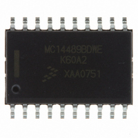
MC14489BDWE Freescale Semiconductor, MC14489BDWE Datasheet - Page 20

MC14489BDWE
Manufacturer Part Number
MC14489BDWE
Description
IC DRIVER LED/LAMP 5CH 20-SOIC
Manufacturer
Freescale Semiconductor
Datasheet
1.MC14489BPE.pdf
(22 pages)
Specifications of MC14489BDWE
Display Type
LED
Configuration
7 Segment
Interface
Serial
Current - Supply
5.5mA
Voltage - Supply
4.5 V ~ 5.5 V
Operating Temperature
-40°C ~ 130°C
Mounting Type
Surface Mount
Package / Case
20-SOIC (7.5mm Width)
Number Of Digits
5
Number Of Segments
40
Low Level Output Current
200 uA
High Level Output Current
17500 uA
Operating Supply Voltage
4.5 V to 5.5 V
Maximum Supply Current
1500 uA
Maximum Operating Temperature
+ 130 C
Mounting Style
SMD/SMT
Minimum Operating Temperature
- 40 C
Lead Free Status / RoHS Status
Lead free / RoHS Compliant
Digits Or Characters
-
Lead Free Status / Rohs Status
Lead free / RoHS Compliant
Available stocks
Company
Part Number
Manufacturer
Quantity
Price
Company:
Part Number:
MC14489BDWE
Manufacturer:
TI
Quantity:
92
Part Number:
MC14489BDWE
Manufacturer:
FREESCALE
Quantity:
20 000
Company:
Part Number:
MC14489BDWER2
Manufacturer:
AMALFI
Quantity:
3 400
temperature (T J ) ranging from – 40 to 130 C, as indicated in
the electrical characteristics tables. The ambient operating
temperature range (T A ) is dependent on R JA , the internal
chip current, how many anode drivers are used, the number
of bank drivers used, the drive current, and how the package
is cooled. The maximum ratings table gives the thermal resis-
tance, junction–to–ambient, of the MC14489B mounted on a
pc board using natural convection to be 90 C per watt for the
plastic DIP. The SOG thermal resistance is 100 C per watt.
power dissipated by the MC14489B.
where
are:
where
maximum allowable ambient temperature.
Worst–Case Analysis Example 1:
5–digit display with decimals (5 banks and 8 anode drivers)
DIP without heat sink on PC board
P D = (20)(8)(5.25 – 1.8)(5/5) = 552 mW
P I = (1.5)(5.25) + 2[5.25 – 2(2)] = 10 mW
Therefore, P T = 552 + 10 = 562 mW
and T chip = R JA P T = (90 C/W)(0.562) = 51 C
Finally, the maximum allowable
MC14489B
20
1.5 mA = Operating supply current of the MC14489B
V LED = Minimum anticipated voltage drop across the
V LED = 1.8 V min
The MC14489B is designed to operate with a chip–junction
The following general equation (1) is used to determine the
The equations for the two terms of the general equation
The following two examples show how to calculate the
T A = T J max – T chip = 130 – 51 = 79 C
V DD = Maximum supply voltage, referenced to V SS
V DD = 5.25 max
i OH = Peak anode driver current (mA)
i OH = 20 mA max
I Rx = i OH /10, with i OH = the peak anode driver current
P D = Power dissipated in the driver circuitry (mW)
P T = Total power dissipation of the MC14489B
Rx = External resistor value (k )
P I = Power dissipated by the internal chip
N = Number of anode drivers used
B = Number of bank drivers used
P I = (1.5 mA)(V DD ) + I Rx (V DD – I Rx Rx)
circuitry (mW)
(mA) when the dimmer bit is high
(volts)
LED
P D = (i OH ) (N)(V DD – V LED )(B/5)
P T = P D + P I
THERMAL CONSIDERATIONS
Ref. (2)
Ref. (3)
Ref. (1)
(1)
(2)
(3)
130 C. The chip’s average temperature for this example is
lower than 130 C because all segments are usually not illumi-
nated simultaneously for an indefinite period.
Worst–Case Analysis Example 2:
16 lamps (4 banks and 4 anode drivers)
SOG without heat sink on PC board
P D = (30)(4)(5.5 – 1.8)(4/5) = 355 mW
P I = (1.5)(5.5) + 3[5.5 – 3(1.0)] = 16 mW
Therefore, P T = 355 + 16 = 371 mW
and T chip = R JA P T = (100 C/W)(0.371) = 37 C
Finally, the maximum allowable
reduce T J , which extends chip life, a heat sink such as shown
in Figure 20 can be used in high–current applications. Alter-
natively, heat–spreader techniques can be used on the PC
board, such as running a wide trace under the MC14489B and
using thermal paste. Wide, radial traces from the MC14489B
leads also act as heat spreaders.
AAVID #5804 or equivalent
(Tel. 603/524–4443, FAX 603/528–1478)
Motorola cannot recommend one supplier over another and
in no way suggests that this is the only heat sink supplier.
QT Optoelectronics
Hewlett–Packard (HP), Components Group
Industrial Electronic Engineers (IEE), Component Products Div.
Purdy Electronics Corp., AND Product Line
V LED = 1.8 V min
That is, if T A = 79 C, the maximum junction temperature is
T A = T J max – T chip = 130 – 37 = 93 C
To extend the allowable ambient temperature range or to
V DD = 5.5 max
Table 3. LED Lamp and Common–Cathode Display
NOTE: Motorola cannot recommend one supplier over another
i OH = 30 mA max
and in no way suggests that this is a complete listing of
LED suppliers.
Figure 20. Heat Sink
Manufacturers
Supplier
MOTOROLA
Ref. (2)
Ref. (3)
Ref. (1)


