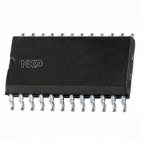
SAA1064T/N2,118 NXP Semiconductors, SAA1064T/N2,118 Datasheet - Page 7

SAA1064T/N2,118
Manufacturer Part Number
SAA1064T/N2,118
Description
IC LED DRIVER W/I2C BUS 24SOIZ
Manufacturer
NXP Semiconductors
Datasheet
1.SAA1064N2112.pdf
(19 pages)
Specifications of SAA1064T/N2,118
Package / Case
24-SOIC (7.5mm Width)
Display Type
LED
Configuration
7 Segment + DP
Interface
I²C
Digits Or Characters
4 Digits
Current - Supply
9.5mA
Voltage - Supply
4.5 V ~ 15 V
Operating Temperature
-40°C ~ 85°C
Mounting Type
Surface Mount
Number Of Digits
4
Low Level Output Current
110 uA
High Level Output Current
100 mA
Operating Supply Voltage
4.5 V to 15 V
Maximum Supply Current
14 mA
Maximum Power Dissipation
500 mW
Maximum Operating Temperature
+ 85 C
Mounting Style
SMD/SMT
Minimum Operating Temperature
- 40 C
Lead Free Status / RoHS Status
Lead free / RoHS Compliant
Lead Free Status / RoHS Status
Lead free / RoHS Compliant, Lead free / RoHS Compliant
Other names
933973520118
SAA1064TD-T
SAA1064TD-T
SAA1064TD-T
SAA1064TD-T
Available stocks
Company
Part Number
Manufacturer
Quantity
Price
Company:
Part Number:
SAA1064T/N2,118
Manufacturer:
MICROCHIP
Quantity:
12 000
Philips Semiconductors
Product specification
2
SAA1064
4-digit LED-driver with I
C-Bus interface
SDA, SCL
2
The SDA and SCL I/O meet the I
C-Bus specification. For protection against positive voltage pulses on these inputs
voltage regulator diodes are connected to V
. This means that normal line voltage should not exceed 5,5 volt. Data will
EE
be latched on the positive-going edge of the acknowledge related clock pulse.
Power-on reset
The power-on reset signal is generated internally and sets all bits to zero, resulting in a completely blanked display. Only
the POWER RESET flag is set.
External Control (C
)
EXT
With a capacitor connected to pin 2 the multiplex frequency can be set (see Fig.5). When static this pin can be connected
to V
or V
or left floating since the oscillator will be switched off.
EE
CC
Segment outputs
The segment outputs P1 to P16 are controllable current-sink sources. They are switched on by the corresponding data
bits and their current is adjusted by control bits C4, C5 and C6.
Multiplex outputs
The multiplex outputs MX1 and MX2 are switched alternately in dynamic mode with a frequency derived from the
clock-oscillator. In static mode MX1 is switched on. The outputs consist of an emitter-follower, which can be used to drive
the common anodes of two displays directly provided that the total power dissipation of the circuit is not exceeded. If this
occurs external transistors should be connected to pins 11 and 14 as shown in Fig.5.
February 1991
7


