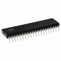
PCF8577CP/F3,112 NXP Semiconductors, PCF8577CP/F3,112 Datasheet - Page 7

PCF8577CP/F3,112
Manufacturer Part Number
PCF8577CP/F3,112
Description
IC LCD DRIVER 32/64SEG 40-DIP
Manufacturer
NXP Semiconductors
Datasheet
1.PCF8577CT3118.pdf
(28 pages)
Specifications of PCF8577CP/F3,112
Package / Case
40-DIP (0.600", 15.24mm)
Display Type
LCD
Configuration
32 Segment
Interface
I²C
Voltage - Supply
2.5 V ~ 6 V
Operating Temperature
-40°C ~ 85°C
Mounting Type
Through Hole
Number Of Digits
32
Number Of Segments
64
Maximum Clock Frequency
100 KHz
Operating Supply Voltage
2.5 V to 6 V
Maximum Power Dissipation
500 mW
Maximum Operating Temperature
+ 150 C
Minimum Operating Temperature
- 65 C
Lead Free Status / RoHS Status
Lead free / RoHS Compliant
Current - Supply
-
Digits Or Characters
-
Lead Free Status / Rohs Status
Details
Other names
568-1081-5
935212300112
PCF8577CPN
935212300112
PCF8577CPN
Philips Semiconductors
6.5
The PCF8577C is set to the direct drive mode by loading
the MODE control bit with logic 0. In this mode only four
bytes are required to store the data for the 32 segment
drivers. Setting the BANK bit to logic 0 selects even bytes
(BANK A), setting the BANK bit to logic 1 selects odd bytes
(BANK B).
In the direct drive mode the SBV is auto-incremented by
two after the loading of each segment byte register. This
means that auto-incremented loading of BANK A or
BANK B is possible. Either bank may be completely or
partially loaded irrespective of which bank is being
displayed. Direct drive output waveforms are shown in
Fig.4.
1998 Jul 30
LCD direct/duplex driver with
I
V
---------------------- -
V
V
2
on(rms)
on rms
off rms
C-bus interface
Direct drive mode
= 0.791 (V
=
2.236
0.5 (V
0.5 (V
V
0.5 (V
0
0.5 (V
(V
V
0.5 (V
0
0.5 (V
(V
DD
V DD
V SS
V DD
V SS
V DD
V SS
DD
DD
DD
DD
V
DD
DD
DD
DD
DD
DD
SS
V
V
V
V
SS
SS
); V
SS
SS
V
V
V
V
V
V
off(rms)
)
)
SS
SS
SS
SS
SS
SS
)
)
)
)
)
)
= 0.354 (V
OFF / OFF
Fig.5 Duplex mode display output waveforms.
DD
V
SS
).
ON / OFF
7
6.6
The PCF8577C is set to the duplex mode by loading the
MODE bit with logic 1. In this mode a second backplane
signal (BP2) is needed and pin A2/BP2 is used for this;
therefore A2 and its equivalent SBV bit V5 are undefined.
The SBV auto-increments by one between loaded bytes.
All of the segment bytes are required to store data for the
32 segment drivers and the BANK bit is ignored.
Duplex mode output waveforms are shown in Fig.5.
OFF / ON
Duplex mode
ON / ON
f
LCD
1
Segment x
BP1
BP2
BP1
BP2
(Sx)
Product specification
MGA738
PCF8577C
Sx
Sx


