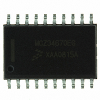
MCZ34670EG Freescale Semiconductor, MCZ34670EG Datasheet - Page 16

MCZ34670EG
Manufacturer Part Number
MCZ34670EG
Description
IC POE CURR MODE SW REG 20-SOIC
Manufacturer
Freescale Semiconductor
Type
Power Over Ethernet Controller (PoE)r
Datasheet
1.MCZ34670EGR2.pdf
(24 pages)
Specifications of MCZ34670EG
Applications
Remote Peripherals (Industrial Controls, Cameras, Data Access)
Internal Switch(s)
No
Voltage - Supply
60V
Operating Temperature
-40°C ~ 85°C
Mounting Type
Surface Mount
Package / Case
20-SOIC (0.300", 7.50mm Width)
Product
PoE / LAN Solutions
Supply Voltage (max)
80 V
Supply Voltage (min)
- 0.3 V
Power Dissipation
800 mW
Operating Temperature Range
- 40 C to + 85 C
Mounting Style
SMD/SMT
Supply Current
18 mA
Output Current
2.1A
Digital Ic Case Style
SOIC
No. Of Pins
20
Duty Cycle (%)
48%
Uvlo
2V
Frequency
400kHz
Msl
MSL 3 - 168 Hours
Rohs Compliant
Yes
Lead Free Status / RoHS Status
Lead free / RoHS Compliant
Available stocks
Company
Part Number
Manufacturer
Quantity
Price
Part Number:
MCZ34670EG
Manufacturer:
FREESCALE
Quantity:
20 000
Company:
Part Number:
MCZ34670EGR2
Manufacturer:
KODENSHI
Quantity:
6 400
This reduces power dissipation in the device and improves
overall efficiency.
filtering of the V
for this load capacitor should be at least 10 µF. An electrolytic
type capacitor is sufficient.
information about the size of the capacitor.
regulator is
is held low.
PWM CONTROLLER UVLO, SOFT-START, AND
SHUTDOWN FUNCTION
output voltage to ramp up in a controlled way, thus
eliminating output voltage overshoot.
capacitor C
After coming out of undervoltage lockout, an internal current
source starts charging the capacitor C
When V
PWM operation begins. The duty cycle during soft-start is
primarily controlled by the internal sawtooth voltage and the
voltage at the SS pin. If the voltage at the SS pin is above
2.6 V, the regular PWM control through pins CS, COMP, and
FB takes over and soft-start is finished.
OVERVOLTAGE SHUTDOWN
feature that turns off the external MOSFET when the input
voltage exceeds the overvoltage threshold.
16
34670
FUNCTIONAL DEVICE OPERATION
OPERATIONAL MODES
HVReg enable
GATE enable
V
V
V
Figure 17. V
A load capacitor connected to V
Please refer to application note
If V
The soft-start function provided by the 34670 allows the
While the PWM controller is in undervoltage lockout, the
The following equation calculates the total soft-start time:
The 34670 includes an overvoltage protection (OVP)
REG(OFF)
GATE(R)
GATE(F)
DD
SS
12
10
8
6
4
2
falls below the UVLO threshold, the voltage
has reached 0.6 V, the gate driver is enabled and
SS
disabled and
connected to the SS pin is fully discharged.
DD
DD
t SS ms
and MOSFET Driver Output Behavior
voltage. The minimum capacitance value
[
]
the MOSFET driver output (GATE)
=
0.4 C SS nF
⋅
DD
A/N3279
ensures a proper
SS
[
to initiate soft-start.
]
for further
t
(V
the same time, the slow discharge of C
the soft-start capacitor is discharging, the gate driver remains
disabled. Once V
(V
through a regular soft-start.
CURRENT-SENSE COMPARATOR
circuitry limits the peak current through the MOSFET. Current
is sensed at CS pin as a voltage across the sense resistor
R
limit and a 400 mV low limit. When the voltage on CS
produced by a current through the current sense resistor
exceeds the high limit threshold, the current ON-cycle is
immediately terminated and the GATE output is pulled low.
(typical blanking time), the current ON-cycle is also
terminated. The blanking time ensures a false termination of
the switching cycle caused by the leading-edge spike on the
sense waveform.
the following equation:
where I
current.
current switching cycle is terminated and GATE is pulled low.
The soft-start capacitor C
of the faulty condition the PWM is re-started through a regular
soft start.
PWM OSCILLATOR
of the PWM controller. The frequency of the oscillator can be
adjusted between 100 kHz and 400 kHz by an optional
external resistor R
integrated circuit to V
calculated as shown below:
where f
frequency adjusting resistor.
be connected to V
RESET OUTPUT
circuit supervises the FB voltage and recognizes if the output
CS
PWR
PWR
When the overvoltage protection is triggered
The current-sense (CS) comparators and its associated
The CS input has two voltage trip levels, a
If the low limit threshold is exceeded for longer than 50 ns
The current-sense resistor R
In case of an overcurrent in the external MOSFET the
A default 250 kHz oscillator sets the switching frequency
The appropriate switching frequency f
To use the default frequency of 250 kHz the FREQ pin can
The RESET pin is an open drain output. The reset control
between the source of the MOSFET and V
R CS
> V
< V
PWM
LIM(primary)
OV(R)
OV(F)
=
is the PWM switching frequency and R
----------------------------------------
I LIM primary
f PWM kHz
) condition disappears, operation resumes
), the gate driver is immediately disabled. At
SS
400mV
is the maximum peak primary-side
IN
(
FREQ
= 0.3 V and the overvoltage
[
or can be left open.
IN
Analog Integrated Circuit Device Data
.
connected from the FREQ pin of the
SS
]
)
=
is discharged and after removal
----------------------------------- -
R FREQ kΩ
CS
47920
is selected according to
Freescale Semiconductor
[
SS
PWM
is initiated. While
]
+
4
can be
OUT
600mV high
FREQ
.
is the


