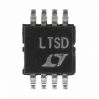
LTC4211IMS8#TRPBF Linear Technology, LTC4211IMS8#TRPBF Datasheet - Page 20

LTC4211IMS8#TRPBF
Manufacturer Part Number
LTC4211IMS8#TRPBF
Description
IC CONTROLLER HOT SWAP 8-MSOP
Manufacturer
Linear Technology
Type
Hot-Swap Controllerr
Datasheet
1.LTC4211IMS8PBF.pdf
(36 pages)
Specifications of LTC4211IMS8#TRPBF
Applications
General Purpose
Internal Switch(s)
No
Voltage - Supply
2.5 V ~ 16.5 V
Operating Temperature
-40°C ~ 85°C
Mounting Type
Surface Mount
Package / Case
8-TSSOP, 8-MSOP (0.118", 3.00mm Width)
Linear Misc Type
Positive Low Voltage
Family Name
LTC4211
Package Type
MSOP
Operating Supply Voltage (min)
2.5V
Operating Supply Voltage (max)
16.5V
Operating Temperature (min)
-40C
Operating Temperature (max)
85C
Operating Temperature Classification
Industrial
Product Depth (mm)
3mm
Product Height (mm)
0.86mm
Product Length (mm)
3mm
Mounting
Surface Mount
Pin Count
8
Lead Free Status / RoHS Status
Lead free / RoHS Compliant
Available stocks
Company
Part Number
Manufacturer
Quantity
Price
OPERATIO
LTC4211
start-up sequence where the LTC4211 is powered up into
a load overcurrent condition. Note that the circuit breaker
trips at Time Point B and is reset at Time Point 9A.
ADJUSTING SLOW COMP’S RESPONSE TIME
The response time of SLOW COMP is adjusted using a
capacitor connected from the LTC4211’s FILTER pin to
ground. If this pin is left unused, SLOW COMP’s delay
defaults to 20µs. During normal operation, the FILTER
output pin is held low as an internal 10µA pull-down
current source is connected to this pin by transistor M4.
This pull-down current source is turned off when an
overcurrent load condition is detected by SLOW COMP.
During an overcurrent condition, the internal 2µA pull-up
current source is connected to the FILTER pin by transis-
tor M5, thereby charging C
capacitor accumulates, the voltage across C
20
V
CC
– V
FILTER
TIMER
RESET
U
FAULT
SENSE
GATE
V
V
OUT
CC
Figure 10. Power-Up in Overcurrent, Slow Comparator Trips the Circuit Breaker
1 2
FILTER
ON
. As the charge on the
V
FB
< V
REF
3 4 5
FAST COMPARATOR ARMED
FILTER
LOAD CURRENT
V
REGULATING
SENSE
6
= 50mV
GATE
V
OUT
increases. Once the FILTER pin voltage increases to 1.236V,
the electronic circuit breaker trips and the LTC4211’s
GATE pin is switched quickly to ground by transistor M3.
After the circuit breaker is tripped, M5 is turned OFF, M4
is turned ON and the 10µA pull-down current then holds
the FILTER pin voltage low.
The SLOW COMP response time from an overcurrent fault
condition to when the circuit breaker trips (GATE OFF) is
given by Equation 7:
For example, if C
time = 638µs. As a design aid, SLOW COMP’s delay time
(t
from 100pF to 1000pF is illustrated in Table 2.
SLOW COMP
t
SLOWCOMP
7 8
SLOW COMPARATOR ARMED
t
FAULTSC
>50mV
2µA
) versus C
CIRCUIT BREAKER TRIPS
B
FPD
V
=
REF
FILTER
10µA
1 236
.
ON
FILTER
= 1000pF, SLOW COMP’s response
t
V
9
RESET
•
9A
CIRCUIT BREAKER RESET
C
for standard values of C
FILTER
2
µ
A
1
ON
+
20
4211 F10
µ
s
FILTER
4211fa
(7)


