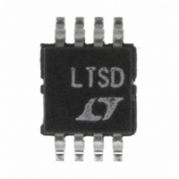
LTC4211IMS8#TRPBF Linear Technology, LTC4211IMS8#TRPBF Datasheet - Page 31

LTC4211IMS8#TRPBF
Manufacturer Part Number
LTC4211IMS8#TRPBF
Description
IC CONTROLLER HOT SWAP 8-MSOP
Manufacturer
Linear Technology
Type
Hot-Swap Controllerr
Datasheet
1.LTC4211IMS8PBF.pdf
(36 pages)
Specifications of LTC4211IMS8#TRPBF
Applications
General Purpose
Internal Switch(s)
No
Voltage - Supply
2.5 V ~ 16.5 V
Operating Temperature
-40°C ~ 85°C
Mounting Type
Surface Mount
Package / Case
8-TSSOP, 8-MSOP (0.118", 3.00mm Width)
Linear Misc Type
Positive Low Voltage
Family Name
LTC4211
Package Type
MSOP
Operating Supply Voltage (min)
2.5V
Operating Supply Voltage (max)
16.5V
Operating Temperature (min)
-40C
Operating Temperature (max)
85C
Operating Temperature Classification
Industrial
Product Depth (mm)
3mm
Product Height (mm)
0.86mm
Product Length (mm)
3mm
Mounting
Surface Mount
Pin Count
8
Lead Free Status / RoHS Status
Lead free / RoHS Compliant
Available stocks
Company
Part Number
Manufacturer
Quantity
Price
APPLICATIO S I FOR ATIO
FAULT is asserted low (but not latched) to indicate a start-
up failure. Only if the input overvoltage condition is re-
moved before Time Point 5 does the start-up sequence
resume at the second timing cycle. At this point in time, the
GATE pin voltage is allowed to ramp up, FAULT is pulled
to logic high and the circuit breaker is armed. Should, at
any time after Time Point 5, a supply overvoltage condition
develop (V
will trip, the GATE will be pulled low to turn off the external
MOSFET and FAULT will be asserted low and latched. This
sequence is shown in detail at Time Point B.
FILTER
TIMER
RESET
FAULT
GATE
V
V
OUT
CC
FILTER
1
> 1.236V), the electronic circuit breaker
2
>V
ON
U
REF
– 80mV
U
2A
OVERVOLTAGE
DUE TO A START-UP OVERVOLTAGE PROBLEM
FAULT IS PULLED LOW (BUT NOT LATCHED)
W
3
4
Figure 24. High Side Overvoltage Protection
IF OVERVOLTAGE GOES
AWAY, SECOND CYCLE
U
CONTINUES
IF ANY FAULT HAPPENS
AFTER THIS POINT, THE
CIRCUIT BREAKER TRIPS
AND FAULT LATCHES LOW
5
Low Side (Output) Overvoltage Protection
A Zener diode can be used in a similar fashion to detect/
protect the system against a supply overvoltage condition
on the load (or low) side of the pass transistor. In this case,
the Zener diode is connected from the load to the LTC4211’s
FILTER pin, as shown in Figure 25. An additional diode,
D1, prevents the FILTER pin from pulling low during an
output short-circuit. Figure 26 illustrates the timing dia-
gram for a low side output overvoltage condition. In this
example, the LTC4211 can only sense the overvoltage
supply condition after Time Point 5 and the GATE pin has
6
POWER GOOD
V
FB
> V
GATE
V
OUT
REF
SLOW COMPARATOR ARMED
7
8
>V
REF
FPD
A B C
OVERVOLTAGE CIRCUIT BREAKER
TRIPS, GATE PULLS DOWN AND
FAULT LATCHES LOW
POWER BAD
V
FB
4211 F24
FAULT
LATCHED LOW
< V
REF
LTC4211
31
4211fa


