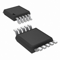
LM5067MMX-2/NOPB National Semiconductor, LM5067MMX-2/NOPB Datasheet - Page 18

LM5067MMX-2/NOPB
Manufacturer Part Number
LM5067MMX-2/NOPB
Description
IC CTLR NEG HOTSWAP A/R 10MSOP
Manufacturer
National Semiconductor
Type
Hot-Swap Controllerr
Datasheet
1.LM5067MM-1NOPB.pdf
(24 pages)
Specifications of LM5067MMX-2/NOPB
Applications
General Purpose
Internal Switch(s)
No
Voltage - Supply
-9 V ~ -80 V
Operating Temperature
-40°C ~ 125°C
Mounting Type
Surface Mount
Package / Case
10-TFSOP, 10-MSOP (0.118", 3.00mm Width)
Linear Misc Type
Negative Voltage
Family Name
LM5067-2
Package Type
MSOP
Operating Supply Voltage (min)
-9V
Operating Supply Voltage (max)
-80V
Operating Temperature (min)
-40C
Operating Temperature (max)
125C
Operating Temperature Classification
Automotive
Product Depth (mm)
3mm
Product Height (mm)
0.86mm
Product Length (mm)
3mm
Mounting
Surface Mount
Pin Count
10
For Use With
LM5067EVAL - NEGATIVE HOT SWAP / INRUSH CURRE
Lead Free Status / RoHS Status
Lead free / RoHS Compliant
Other names
LM5067MMX-2
Available stocks
Company
Part Number
Manufacturer
Quantity
Price
Company:
Part Number:
LM5067MMX-2/NOPB
Manufacturer:
TI
Quantity:
4 500
www.national.com
The procedure to calculate the resistor values is as follows:
Q1, and the lower UVLO threshold (V
Q1.
be chosen in advance in this case, but is determined after the
values for R1-R3 are determined. If V
defined in addition to the other three thresholds, see Option
B below.
The resistors are calculated as follows:
The lower OVLO threshold is calculated from:
As an example, assume the application requires the following
thresholds: V
The lower OVLO threshold calculates to -55.8V, and the OV-
LO hysteresis is 4.2V. Note that the OVLO hysteresis is
always slightly greater than the UVLO hysteresis in this con-
figuration.
When the R1-R3 resistor values are known, the threshold
voltages and hysteresis are calculated from the following:
- The lower OVLO threshold (V
- Determine the upper OVLO threshold (V
- Determine the upper UVLO threshold (V
UVH
= -36V, V
UVL
= -32V, V
OVL
), to enable Q1, cannot
UVL
OVL
OVH
) to disable Q1.
must be accurately
= -60V.
OVH
UVH
) to disable
) to enable
18
Note: Ensure the voltages at the UVLO and OVLO pins do
not exceed the Absolute Maximum ratings for those pins
when the system voltage is at maximum.
Option B: If all four thresholds must be accurately defined,
the configuration in Figure 12 can be used.
The four resistor values are calculated as follows:
and the lower UVLO threshold (V
Q1, and the lower OVLO threshold (V
- Determine the upper UVLO threshold (V
- Determine the upper OVLO threshold (V
FIGURE 12. Programming the Four Thresholds
UVL
) to disable Q1.
OVL
) to enable Q1.
UVH
OVH
) to enable Q1,
) to disable
30030951


