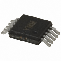
SY88722VKC Micrel Inc, SY88722VKC Datasheet - Page 4

SY88722VKC
Manufacturer Part Number
SY88722VKC
Description
IC LASR DRVR 622MBPS 5.5V 10MSOP
Manufacturer
Micrel Inc
Type
Laser Diode Driver (Fiber Optic)r
Specifications of SY88722VKC
Number Of Channels
1
Data Rate
622Mbps
Voltage - Supply
3 V ~ 3.6 V, 4.5 V ~ 5.5 V
Current - Supply
25mA
Current - Modulation
30mA
Operating Temperature
-40°C ~ 85°C
Package / Case
10-TFSOP, 10-MSOP (0.118", 3.00mm Width)
Mounting Type
Surface Mount
Operating Supply Voltage (typ)
3.3/5V
Operating Temperature (min)
0C
Mounting
Surface Mount
Operating Temperature Classification
Commercial
Lead Free Status / RoHS Status
Contains lead / RoHS non-compliant
Micrel, Inc.
50
with the on-board 50
25
creates a voltage swing which can be used to measure
various performance parameters of the SY88722V. The
current is adjustable through the use of potentiometer R5.
With the SY88722V evaluation board, you can measure the
following:
M9999-102405
hbwhelp@micrel.com or (408) 955-1690
MEASUREMENTS
The SY88722V evaluation board assumes the use of a
1. Eye pattern generation including jitter, rise/fall
scope to terminate the SY88722V. This, in parallel
output load. The current passing through this load
Figure 3. Typical SY88722V Eye Diagram
times and modulation current verification.
a) Adjust R5 to give 750mV (1.25V
b) Press Autoscale on oscilloscope. The eye
c) Observe measurements on scope’s display.
d) Adjust R5 to give 125mV (250mV
amplitude (I
should be approximately 1k . The power
supply needs to be turned off to get a correct
reading of the potentiometer’s resistance.
pattern should automatically display on the
scope. If not, verify the steps listed in the
“Setup for Measurements” section are
completed. Sometimes the waveform needs
to be manually adjusted to fit the display. Use
the Time Scale and Voltage Scale knobs on
the front panel of the scope to adjust this.
The rise and fall times should be less than
400ps, amplitude around 750mV, and jitter
around 10ps
amplitude (I
repeat above. R5 should be around 8k
TIME (400ps/div.)
mod
mod
output pull-up resistors, creates a
rms
.
= 30mA = 1.25V/0.025k ). R5
= 5mA = 0.125V/0.025k ) and
pp
pp
) output
) output
4
2. Mask testing:
3. BER testing:
a) Press Eye/Mask Mode on front panel of scope.
b) Choose Mask Testing from on-screen display.
c) Choose Open Mask from on-screen selection
d) Choose Start Mask Testing from on-screen
a) Since the SY88722V is designed to drive a
b) Feedback the 70843V’s Clock output to the
c) Set the 88722V’s modulation current to a
d) From the 70004A’s Gating menu:
no
list.
selection list. Waveform should automatically
display with appropriate mask regions and
testing will start. If not, verify the steps listed in
the “Setup for Measurements” section are
completed.
laser, where an optical HIGH means the laser
is conducting, the SY88722V will electrically be
LOW. Hence, the output polarity is opposite of
the input polarity. Since this is the case, it is
recommended to feedback the SY88722V
evaluation board’s /OUT output to the 70843B’s
BERT data input. The alternative is to feedback
the SY88722V evaluation board’s OUT output
to the 70843V’s BERT data input, but to select
inverted polarity from the 70004A’s Data menu.
70843V’s BERT Clock input.
desired value using R5 as described in Section
1 of this page. Remember, I
V
iv. 70004A will reset error count and synchro-
iii. Choose run gating.
v. At end of the gating period, there should be
ii. Choose single gating period.
i. Select and open the OC-12 mask.
amp
i. Choose a gate condition. The options are:
gate by time, errors or bits. Choose bits,
but this is of no relevance because there
should be no errors, and the test will run
forever until manually interrupted if gate by
errors is chosen.
nize SY88722V’s transmitted bitstream to
70843V’s generated bitstream. If synchro-
nization does not occur, it is sometimes
due to cable length. Try using different
length cables to achieve synchronization. If
this is unavailable, another trick is to adjust
the 83752A’s frequency to a slightly higher
or lower value.
(V)/0.025k .
errors.
SY88722V Evaluation Board
mod
(mA) =


