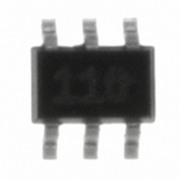
ZXLD1100H6TA Diodes Zetex, ZXLD1100H6TA Datasheet - Page 8

ZXLD1100H6TA
Manufacturer Part Number
ZXLD1100H6TA
Description
IC LED DRVR WHITE BCKLGT SC-70-6
Manufacturer
Diodes Zetex
Type
Backlight, White LEDr
Datasheet
1.ZXLD1100H6TA.pdf
(16 pages)
Specifications of ZXLD1100H6TA
Topology
PWM, Step-Up (Boost)
Number Of Outputs
1
Internal Driver
Yes
Type - Primary
Backlight
Type - Secondary
White LED
Frequency
1MHz
Voltage - Supply
2.5 V ~ 5.5 V
Voltage - Output
28V
Mounting Type
Surface Mount
Package / Case
SC-70-6, SC-88, SOT-363
Operating Temperature
-40°C ~ 85°C
Current - Output / Channel
50mA
Internal Switch(s)
Yes
Efficiency
80%
Lead Free Status / RoHS Status
Lead free / RoHS Compliant
Other names
UZXLD1100H6TA
UZXLD1100H6TR
UZXLD1100H6TR
ZXLD1100H6TR
UZXLD1100H6TR
UZXLD1100H6TR
ZXLD1100H6TR
Available stocks
Company
Part Number
Manufacturer
Quantity
Price
Part Number:
ZXLD1100H6TA
Manufacturer:
ZETEX
Quantity:
20 000
APPLICATIONS
Programming the maximum LED current
The maximum LED current is programmed by adding a
single resistor in series with the LED chain. The current
is determined by the resistor value and feedback
voltage and is given by:
The table below gives recommended resistor values
for required LED currents:
Dimming Control via a PWM signal on the EN pin
A Pulse Width Modulated (PWM) signal can be applied
to the EN pin in order to adjust the output current to a
value below the maximum LED current. Two modes of
adjustment are possible as described below.
True Analog Dimming - Filtered ‘DC’ mode
If a PWM signal of 10kHz or higher is applied to the EN
pin, the device will remain active when the EN pin is
low. However, the input to the internal low pass filter
will be switched alternately from V
duty cycle (D) corresponding to that of the PWM signal.
This will present a filtered dc voltage equal to the duty
cycle multiplied by V
produce a dc output current lower than the maximum
set value. This current is given by:
This mode of adjustment minimizes flicker in the light
output and system noise.
Pulsed Dimming - Gated Mode
If a lower frequency of 1kHz or less is applied to the EN
pin, the device will be gated ‘on’ and ‘off’ at a duty cycle
(D) corresponding to that of the input signal. The
average output current is then given by:
This mode may be preferred over dc current control if
the purest white output is required. However, note the
120 s nominal turn-off delay of the device, when using
the device in this mode.
ZXLD1100
LED Current
10mA
15mA
20mA
30mA
S E M I C O N D U C T O R S
I
where V
LED
I
I
OUTavg
= V
OUTdc
REF
FB
FB
/R1
=100mV
= 0.1D/R1
to the control loop and will
» 0.1D/R1
R1 Value
10
6.8
5
3.3
REF
to ground, with a
8
Dimming Control using a DC voltage
For applications where the EN pin is not available a DC
voltage can be used to control dimming. By adding
resistors R2 and R3 and applying a DC voltage, the LED
current can be adjusted from 100% to 0%. As the DC
voltage increases, the voltage drop across R2 increases
and the voltage drop across R1 decreases, thus
reducing the current through the LEDs. Selection of R2
and R3 should ensure that the current from the DC
voltage is much less than the LED current and much
larger than the feedback current. The component
values in the diagram below represent 0% to 100%
dimming control from a 0 to 2V DC voltage.
Dimming Control using a logic signal
For applications where the LED current needs to be
adjusted in discrete steps a logic signal can be applied
as shown in the diagram below. When Q1 os ‘off’, R1
sets the minimum LED current. When Q1 is ‘on’, R2 sets
the LED current that will be added to the minimum LED
current. The formula for selecting values for R1 and R2
are given below:
MOSFET ‘off’
MOSFET ‘on’
where V
I
I
LED MIN
LED MAX
(
(
FB
= 100mV
)
)
R
V
R
V
LED
FB
LED
FB
I
LED MIN
(
)
ISSUE 4 - JULY 2004


