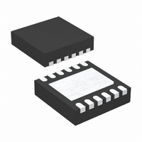
LT3498EDDB#TRMPBF Linear Technology, LT3498EDDB#TRMPBF Datasheet - Page 9

LT3498EDDB#TRMPBF
Manufacturer Part Number
LT3498EDDB#TRMPBF
Description
IC LED DRVR WT/OLED BCKLGT 12DFN
Manufacturer
Linear Technology
Type
Backlight, OLED, White LEDr
Datasheet
1.LT3498EDDBTRMPBF.pdf
(24 pages)
Specifications of LT3498EDDB#TRMPBF
Topology
PWM, Step-Up (Boost)
Number Of Outputs
1
Internal Driver
Yes
Type - Primary
Backlight
Type - Secondary
OLED, White LED
Frequency
1.8MHz ~ 2.8MHz
Voltage - Supply
2.5 V ~ 12 V
Voltage - Output
32V
Mounting Type
Surface Mount
Package / Case
12-DFN
Operating Temperature
-40°C ~ 85°C
Current - Output / Channel
20mA
Internal Switch(s)
Yes
No. Of Outputs
2
Output Current
200mA
Output Voltage
32V
Input Voltage
2.5V To 12V
Dimming Control Type
PWM / DC
Operating Temperature Range
-40°C To +85°C
Driver Case Style
DFN
Rohs Compliant
Yes
Lead Free Status / RoHS Status
Lead free / RoHS Compliant
Efficiency
-
Other names
LT3498EDDB#TRMPBFTR
Available stocks
Company
Part Number
Manufacturer
Quantity
Price
OPERATION— OLED DRIVER
The low noise boost of the LT3498 uses a novel control
scheme to provide high effi ciency over a wide range
of output current. In addition, this technique keeps the
switching frequency above the audio band over all load
conditions.
The operation of the part can be better understood by
referring to the Block Diagram. The part senses the
output voltage by monitoring the voltage on the FB2 pin.
The user sets the desired output voltage by choosing the
value of the external topside feedback resistor. The part
incorporates a precision 182kΩ bottom-side feedback
resistor. Assuming that output voltage adjustment is not
used (CTRL2 pin is tied to 1.5V, or greater), the internal
reference (V
will servo during regulation.
The Switch Control block senses the output of the ampli-
fi er and adjusts the switching frequency, as well as other
APPLICATIONS INFORMATION— LED DRIVER
Inductor Selection
A 15μH inductor is recommended for most applications
for the LED driver of the LT3498. Although small size and
high effi ciency are major concerns, the inductor should
have low core losses at 2.3MHz and low DCR (copper
wire resistance). Some small inductors in this category
are listed in Table 1. The effi ciency comparison of different
inductors is shown in Figure 2.
Table 1: Recommended Inductors
PART
LQH32CN150K53
LQH2MCN150K02
LQH32CN100K53
LQH2MCN100K02
SD3110-150
1001AS-150M
(TYPE D312C)
D03314-153ML
REF
= 1.215V) sets the voltage to which FB2
(μH)
15
15
10
10
15
15
15
L
0.764
MAX
DCR
0.58
0.80
0.86
(Ω)
1.6
0.3
1.2
CURRENT
RATING
(mA)
300
200
450
225
380
360
680
VENDOR
Murata
www.murata.com
Cooper
www.cooperet.com
Toko
www.toko.com
Coilcraft
www.coilcraft.com
parameters to achieve regulation. During the start-up of
the circuit, special precautions are taken to ensure that
the inductor current remains under control.
Because the switching frequency is never allowed to fall
below approximately 50kHz, a minimum load must be
present to prevent the output voltage from drifting too
high. This minimum load is automatically generated within
the part via the Shunt Control block. The level of this current
is adaptable, removing itself when not needed to improve
effi ciency at higher load levels.
The low-noise boost of the LT3498 also has an integrated
Schottky diode and PMOS output disconnect switch. The
PMOS switch is turned on when the part is enabled. When
the part is in shutdown, the PMOS switch turns off, allowing
the V
function is often required in power supplies.
Capacitor Selection
The small size of ceramic capacitors makes them ideal for
LT3498 LED driver applications. Use only X5R and X7R
types, because they retain their capacitance over wider
temperature ranges than other types, such as Y5V or
Z5U. A 4.7μF input capacitor and a 1μF output capacitor
are suffi cient for most applications.
Figure 2. Effi ciency Comparison of Different Inductors
OUT2
node to go to ground. This type of disconnect
80
55
50
45
75
70
65
60
0
5
LED CURRENT (mA)
15uH Murata LQH32CN150K53
15uH Murata LQH2MCN150K02
15uH Cooper SD3110-150
15uH Toko D312C
15uH Coilcraft DO3314-153ML
10
15
3498 F02
LT3498
20
3498fa
9


