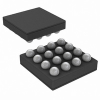
LM3554TME/NOPB National Semiconductor, LM3554TME/NOPB Datasheet - Page 15

LM3554TME/NOPB
Manufacturer Part Number
LM3554TME/NOPB
Description
IC LED DVR PHOTO FLASH 16-USMD
Manufacturer
National Semiconductor
Type
Photo Flash LED (I²C Interface)r
Datasheet
1.LM3554TMENOPB.pdf
(40 pages)
Specifications of LM3554TME/NOPB
Constant Current
Yes
Topology
High Side, Step-Up (Boost)
Number Of Outputs
2
Internal Driver
Yes
Type - Primary
Flash/Torch
Type - Secondary
White LED
Frequency
2MHz
Voltage - Supply
2.7 V ~ 5.5 V
Voltage - Output
5V
Mounting Type
Surface Mount
Package / Case
16-MicroSMD
Operating Temperature
-30°C ~ 85°C
Current - Output / Channel
600mA
Internal Switch(s)
Yes
Efficiency
90%
Led Driver Application
LED Backlighting, Portable Electronics
No. Of Outputs
2
Output Current
1.2A
Input Voltage
2.7V To 5.5V
Dimming Control Type
I2C
Rohs Compliant
Yes
Lead Free Status / RoHS Status
Lead free / RoHS Compliant
Other names
LM3554TMETR
Block Diagram
Overview
The LM3554 is a high-power white LED flash driver capable
of delivering up to 1.2A of LED current into a single LED, or
up to 600mA into two parallel LEDs. The device incorporates
a 2MHz constant frequency, synchronous, current mode
PWM boost converter, and two high-side current sources to
regulate the LED current over the 2.5V to 5.5V input voltage
range.
The LM3554 operates in two modes: LED mode or constant
Voltage Output mode. In LED mode when the output voltage
is greater than V
maintains at least 300mV (V
(LED1 and LED2). This minimum headroom voltage ensures
that the current sinks remain in regulation. When the input
voltage is above V
mode with the device not switching and the PFET on contin-
uously. In Pass mode the difference between (V
I
If the device is operating in Pass mode, and V
point that forces the device into switching, the LM3554 will
make a one-time decision to jump into switching mode. The
LM3554 remains in switching mode until the device is shut-
down and re-enabled. This is true even if V
above V
This prevents the LED current from oscillating when V
operating close to V
LED
×R
ON_P
LED
) and V
+ 300mV during the current Flash or Torch cycle.
IN
– 150mV, the PWM converter switches and
LED
LED
OUT
is dropped across the current sources.
+ V
.
HR
HR
, the device operates in Pass
) across both current sources
IN
were to rise back
IN
drops to a
IN
IN
is
-
15
In Voltage Output mode the LM3554 operates as a voltage
output boost converter with selectable output voltages of 4.5V
and 5V. In this mode the LM3554 is able to deliver up to typ-
ically 5W of output power. At light loads and in Voltage Output
mode the PWM switching converter changes over to a pulsed
frequency regulation mode and only switches as necessary
to ensure proper LED current or output voltage regulation.
This allows for improved light load efficiency compared to
converters that operate in fixed-frequency PWM mode at all
load currents.
Additional features of the LM3554 include 4 logic inputs, an
internal comparator for LED thermal sensing, and a low-pow-
er indicator LED current source. The STROBE input provides
a hardware Flash mode enable. The ENVM/TX2/GPIO2 input
is configurable as a hardware Voltage Output mode enable
(ENVM), an active high Flash interrupt that forces the device
from FLASH mode to a low-power TORCH mode (TX2), or as
a programmable logic input/output (GPIO2). The TX1 input is
configurable as an active high Flash interrupt that forces the
device from FLASH mode to a low-power TORCH mode
(TX1), as a hardware Torch mode enable (TORCH), or as a
programmable logic input/output (GPIO1) . The HWEN input
provides for an active low hardware shutdown of the device.
Finally, the LEDI/NTC pin is configurable as a low-power in-
dicator LED driver (LEDI), or as a threshold detector for
thermal sensing (NTC). In NTC mode when the threshold
(V
TRIP
) at the LEDI/NTC pin is crossed (V
LEDI/NTC
30042005
www.national.com
falling), the


