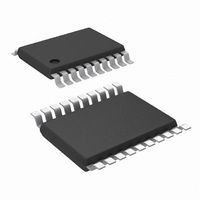
LM3424MH/NOPB National Semiconductor, LM3424MH/NOPB Datasheet - Page 13

LM3424MH/NOPB
Manufacturer Part Number
LM3424MH/NOPB
Description
IC LED DVR BUCK/BOOST 20-TSSOP
Manufacturer
National Semiconductor
Series
PowerWise®r
Type
High Power, Constant Currentr
Datasheet
1.LM3424MHNOPB.pdf
(50 pages)
Specifications of LM3424MH/NOPB
Constant Current
Yes
Topology
Flyback, PWM, SEPIC, Step-Down (Buck), Step-Up (Boost)
Number Of Outputs
1
Internal Driver
No
Type - Primary
Automotive
Type - Secondary
High Brightness LED (HBLED)
Frequency
2MHz
Voltage - Supply
4.5 V ~ 75 V
Mounting Type
Surface Mount
Package / Case
20-TSSOP Exposed Pad, 20-eTSSOP, 20-HTSSOP
Operating Temperature
-40°C ~ 125°C
Current - Output / Channel
1A
Internal Switch(s)
Yes
Efficiency
96%
Lead Free Status / RoHS Status
Lead free / RoHS Compliant
Voltage - Output
-
Other names
LM3424MH
THERMAL FOLDBACK / ANALOG DIMMING
Thermal foldback is necessary in many applications due to
the extreme temperatures created in LED environments. In
general, two functions are necessary: a temperature break-
point (T
be reduced, and a slope corresponding to the amount of LED
current decrease per temperature increase as shown in
ure
breakpoint and slope of the thermal foldback profile.
Foldback is accomplished by adding current (I
summing node. As more current is added, less current is
needed from the high side amplifier and correspondingly, the
LED current is regulated to a lower value. The final tempera-
ture (T
be needed from the high-side amplifier, yielding I
Figure 4
implemented in the system. I
voltage (V
V
R
V
perature increases, voltage should decrease).
An NTC thermistor is the most cost effective device used to
sense temperature. As the temperature of the thermistor in-
creases, its resistance decreases (albeit non-linearly). Usu-
ally, the NTC manufacturer's datasheet will detail the
resistance-temperature characteristic of the thermistor. The
thermistor will have a different resistance (R
TREF
TSENSE
REF2
5. The LM3424 allows the user to program both the
) supplied from the V
can be set with a simple resistor divider (R
END
BK
FIGURE 5. Ideal Thermal Foldback Profile
shows how the thermal foldback circuitry is physically
is set with a temperature dependant voltage (as tem-
) after which the nominal operating current needs to
DIF
) is reached when I
= V
TREF
– V
TSENSE
S
voltage reference (typical 2.45V).
TF
TF
is set by placing a differential
) across TSENSE and TREF.
= I
CSH
causing no current to
NTC
FIGURE 4. Thermal Foldback Circuitry
300857c2
TF
) at each tem-
) to the CSH
LED
REF1
= 0A.
Fig-
and
13
perature. The nominal resistance of an NTC is the resistance
when the temperature is 25°C (R
this will be given a multiplier of 1. Then the resistance at a
higher temperature will have a multiplier less than 1 (i.e. R
multiplier is 0.161 therefore R
sired T
temperatures (R
Using the NTC method, a resistor divider from V
plemented with a resistor connected between V
TSENSE and the NTC thermistor placed at the desired loca-
tion and connected from TSENSE to GND. This will ensure
that the desired temperature-voltage characteristic occurs at
TSENSE.
If a linear decrease over the foldback range is necessary, a
precision temperature sensor such as the LM94022 can be
used instead as shown in
to set V
rest of this datasheet, the NTC method will be used for thermal
foldback calculations.
During operation, if V
is less than T
late its output to zero forcing I
nominal LED current and no foldback is observed.
At T
manufacturer's datasheet for the NTC thermistor, R
be obtained for the desired T
at the breakpoint (V
A general rule of thumb is to set R
breakpoint relationship to R
If V
regulate its output equal to the input forcing V
resistor (R
mately sets the slope of the LED current decrease with re-
spect to increasing temperature by changing I
DIF
BK
, V
> 0V (temperature is above T
BK
TSENSE
DIF
and T
GAIN
= 0V exactly and I
BK
according to the temperature. However, for the
) connected from TGAIN to GND. R
END
and the differential sense amplifier will regu-
NTC-BK
, the corresponding resistances at those
TSENSE-BK
DIF
and R
Figure
< 0V, then the sensed temperature
BIAS
NTC-END
BK
= V
85
TF
4. Either method can be used
= R
and the voltage relationship
= 0.161 x R
TF
25
TREF
REF1
is still zero. Looking at the
) and in many datasheets
BK
NTC-BK
= 0. This maintains the
) can be found.
) can be defined:
), then the amplifier will
= R
REF2
.
25
TF
simplifying the
). Given a de-
DIF
:
S
www.national.com
can be im-
across the
NTC-BK
GAIN
300857a1
S
and
can
ulti-
85


