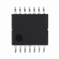
LX1744CPW Microsemi Analog Mixed Signal Group, LX1744CPW Datasheet - Page 12

LX1744CPW
Manufacturer Part Number
LX1744CPW
Description
IC LED DRVR WT/CLR BCKLT 14TSSOP
Manufacturer
Microsemi Analog Mixed Signal Group
Type
Backlight, White LED, Color LEDr
Datasheet
1.LX1744CPW.pdf
(16 pages)
Specifications of LX1744CPW
Constant Current
Yes
Topology
PWM, Step-Up (Boost)
Number Of Outputs
2
Internal Driver
Both
Type - Primary
Backlight
Type - Secondary
Color, White LED
Voltage - Supply
1.6 V ~ 6 V
Voltage - Output
25V
Mounting Type
Surface Mount
Package / Case
14-TSSOP
Operating Temperature
-40°C ~ 85°C
Current - Output / Channel
100mA
Internal Switch(s)
Yes
Efficiency
90%
Lead Free Status / RoHS Status
Lead free / RoHS Compliant
Frequency
-
Available stocks
Company
Part Number
Manufacturer
Quantity
Price
Company:
Part Number:
LX1744CPW
Manufacturer:
Microsemi Analog Mixed Signal
Quantity:
135
Copyright © 2000
Rev. 1.1b, 2005-03-01
Notes
R11, R12, R13
LED1, LED2,
LED3, LED4
CR1, CR2,
CR3, CR4
C10, C12
R9, R10
1.
C2, C7
C3, C4
C5, C6
C8, C9
R1, R3
R2, R6
R7, R8
L1, L2
Note: All pins are referenced to ground.
I N T E G R A T E D
C11
Ref
Q1
C1
R4
R5
U1
Jumper
Use these locations to insert additional input and/or output capacitance.
J1
J2
J3
J4
CAPACITOR, 4.7 µ F, 1210, 6.3V
CAPACITOR, 4.7 µ F, 1210, 35V
CAPACITOR, 1000pF, 0805, 35V
CAPACITOR, (SPARE), See Note 1
CAPACITOR, 1 µ F, 0805, 35V
CAPACITOR, 0.1 µ F, 0805, 6.3V
CAPACITOR, 2.2 µ F, 0805, 16V
Microsemi UPS5819, SCHOTTKY, 1A, 40V, POWERMITE
Microsemi UPWLEDxx, LED, Optomite
INDUCTOR, 47 µ H, 480mA, SMT
FDV303N MOSFET, 30V, SOT-23
RESISTOR, 1M, 1/16W, 0805
RESISTOR, 75K, 1/16W, 0805
RESISTOR, 1K, 1/16W, 0805
RESISTOR, 15, 1/16W, 0805
RESISTOR, 100K, POT, 1/16W, 0805
RESISTOR, 100K, 1/16W, 0805
RESISTOR, 10K, 1/16W, 0805
Microsemi LX1744CPW BOOST CONTROLLER
11861 Western Avenue, Garden Grove, CA. 92841, 714-898-8121, Fax: 714-893-2570
Position
N/A
N/A
N/A
N/A
P R O D U C T S
Table 4: Factory Installed Component List
Table 3: Jumper Position Assignments
Close to adjust LED current with on-board potentiometer.
Close to adjust VLCD with on-board potentiometer.
Remove the factory installed jumper and insert a 4~6cm wire loop
(optional) to observe the inductor current waveform using a current
probe.
Remove jumper to test open-circuit over-voltage protection implemented
with R1 and R2
E V A L U A T I O N B O A R D
Integrated Products Division
Microsemi
Dual Output Boost – LED Driver / LCD Bias
Part Description
Function
P
RODUCTION
D
ATASHEET
LX1744
Page 12


