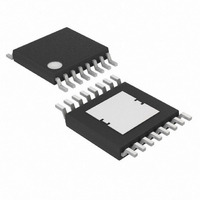
MAX16825AUE+ Maxim Integrated Products, MAX16825AUE+ Datasheet - Page 6

MAX16825AUE+
Manufacturer Part Number
MAX16825AUE+
Description
IC LED DRVR HIGH BRIGHT 16-TSSOP
Manufacturer
Maxim Integrated Products
Type
HBLED Driverr
Datasheet
1.MAX16824AUE.pdf
(13 pages)
Specifications of MAX16825AUE+
Constant Current
Yes
Topology
Linear, Open Drain, PWM
Number Of Outputs
3
Internal Driver
Yes
Type - Primary
Automotive, Backlight
Type - Secondary
High Brightness LED (HBLED)
Voltage - Supply
6.5 V ~ 28 V
Voltage - Output
36V
Mounting Type
Surface Mount
Package / Case
16-TSSOP Exposed Pad, 16-eTSSOP, 16-HTSSOP
Operating Temperature
-40°C ~ 125°C
Current - Output / Channel
150mA
Internal Switch(s)
Yes
Number Of Segments
6
Operating Supply Voltage
6.5 V to 28 V
Maximum Power Dissipation
1500 mW
Maximum Operating Temperature
+ 125 C
Mounting Style
SMD/SMT
Minimum Operating Temperature
- 40 C
Lead Free Status / RoHS Status
Lead free / RoHS Compliant
Frequency
-
Efficiency
-
Lead Free Status / Rohs Status
Details
High-Voltage, Three-Channel Linear
High-Brightness LED Drivers
6
MAX16824
5, 6, 10, 14
_______________________________________________________________________________________
11
12
13
15
16
—
—
—
—
—
—
1
2
3
4
7
8
9
PIN
MAX16825
5, 14
11
12
13
15
16
10
—
—
—
—
1
2
3
4
7
8
9
6
NAME
PWM1
PWM2
PWM3
DOUT
OUT1
OUT3
OUT2
GND
REG
N.C.
CLK
CS1
CS3
CS2
DIN
OE
LE
EP
IN
Channel 1 LED Driver Output. OUT1 is an open-drain, constant-current-sinking output
rated to 36V.
Channel 1 Sense Amplifier Negative Input. Connect a current-sense resistor between
CS1 and GND to program the output current level for channel 1.
Positive Input Supply. Bypass with a 0.1μF (min) capacitor to GND.
+5V-Regulated Output. Connect a 1μF capacitor from REG to GND.
No Connection. Must be left unconnected.
Dimming Input 1. PWM1 is a dimming input for channel 1. A logic-low turns off OUT1 and
a logic-high turns on OUT1.
Dimming Input 2. PWM2 is a dimming input for channel 2. A logic-low turns off OUT2 and
a logic-high turns on OUT2.
Dimming Input 3. PWM3 is a dimming input for channel 3. A logic-low turns off OUT3 and
a logic-high turns on OUT3.
Ground
Channel 3 LED Driver Output. OUT3 is an open-drain, constant-current-sinking output
rated to 36V.
Channel 3 Sense Amplifier Negative Input. Connect a current-sense resistor between
CS3 and GND to program the output current level for channel 3.
Channel 2 Sense Amplifier Negative Input. Connect a current-sense resistor between
CS2 and GND to program the output current level for channel 2.
Channel 2 LED Driver Output. OUT2 is an open-drain, constant-current-sinking output
rated to 36V.
Serial-Data Input. Data is loaded into the internal 3-bit shift register on the rising edge of
CLK.
Latch-Enable Input. Data loaded transparently from the internal shift register to the
output latch while LE is high. Data is latched into the output latch on the LE’s falling edge
and retained while LE is low.
Output Enable Input. Drive OE high to place all outputs into a high-impedance mode
without altering the contents of the output latches. Drive OE low to force all outputs to
follow the state of the output latches.
Serial-Data Output. Data is clocked out of the internal 3-bit shift register to DOUT on the
rising edge of CLK. DOUT is a replica of the shift register’s last bit.
Clock Input
Exposed Pad. Connect EP to a large-area ground plane for effective power dissipation.
Do not use as the IC ground connection.
FUNCTION
Pin Description


