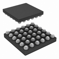
LP55281RLX/NOPB National Semiconductor, LP55281RLX/NOPB Datasheet - Page 16

LP55281RLX/NOPB
Manufacturer Part Number
LP55281RLX/NOPB
Description
IC LED DRIVER RGB 36-USMD
Manufacturer
National Semiconductor
Series
PowerWise®r
Type
RGB LED Driverr
Datasheet
1.LP55281RLNOPB.pdf
(28 pages)
Specifications of LP55281RLX/NOPB
Constant Current
Yes
Topology
PWM, Step-Up (Boost)
Number Of Outputs
12
Internal Driver
Yes
Type - Primary
Light Management Unit (LMU)
Type - Secondary
Color, RGB
Frequency
1MHz ~ 2MHz
Voltage - Supply
3 V ~ 5.5 V
Voltage - Output
4 V ~ 5.3 V
Mounting Type
Surface Mount
Package / Case
36-MicroSMDxt
Operating Temperature
-30°C ~ 85°C
Current - Output / Channel
300mA
Internal Switch(s)
Yes
Efficiency
88%
For Use With
LP55281RLEV - BOARD EVAL FOR LP5528 RGB DRIVER
Lead Free Status / RoHS Status
Lead free / RoHS Compliant
Other names
LP55281RLX
www.national.com
ALED Driver
LP55281 has a single ALED driver. It is a constant current
sink with an 8-bit control. ALED driver can be used as a DC
current sink or an audio synchronized current sink. Note, that
when the audio synchronization function is enabled, the 8-bit
current control register has no effect.
ALED driver is enabled when audio synchronization is en-
abled (EN_SYNC = 1) or when ALED[7:0] control byte has
other than 00h value.
ADJUSTMENT OF ALED DRIVER
Adjustment of the ALED driver current (Register 0Ch) is de-
scribed in table below:
With other than values on the table, the current value can be
calculated to be (15.0 mA / 255) * ALED[7:0], where ALED
[7:0] is value in decimals.
LED Test Interface
All LED pin voltages and boost output voltage in LP55281 can
be measured and value can be read through the SPI/I
compatible interface. MUX_LED[3:0] bits in the LED test reg-
ister (address 12h) are used to select one of the LED outputs
or boost output for measurement. The selected output is con-
nected to the internal ADC through a 55 kΩ resistor divider.
The AD conversion is activated by setting the EN_LTEST bit
to '1'. The first conversion is ready after 128 µs from this. The
result can be read from the ADC output register (address
13h). The device executes the AD conversions automatically
ALED[7:0]
0000 0000
0000 0001
0000 0010
1111 1101
1111 1110
1111 1111
...
Driver Current, mA
(typical)
0.06
14.8
14.9
0.1
15
...
20201107
0
2
C
16
once in every 128 µs period, as long as the EN_LTEST bit is
'1'.
User can set the preferred DC current level with the LED driv-
er controls. The RGB drivers' PWM must be set to 100%, or
otherwise there can appear random variation on results. Note,
that the 55 kΩ resistor divider causes small additional current
through the LED under measurement.
ADC result can be converted into a voltage value (of the se-
lected pin) by multiplying the ADC result (in decimals) with
27.345 mV (value of LSB). The calculated voltage value is the
voltage between the selected pin and ground. The internal
LDO voltage is used as a reference voltage for the conver-
sion. The accuracy of LDO is ± 3%, which is defining the
overall accuracy. The non-linearity and offset figures are both
better than 2LSB.
MUX_LED[3:0]
Principle of LED Connection to ADC
0000
0001
0010
0011
0100
0101
0110
0111
1000
1001
1010
1011
1100
1101
1110
1111
LED Multiplexing (Register 12h)
Boost Output
Connection
ALED
R1
G1
R2
G2
R3
G3
R4
G4
B1
B2
B3
B4
-
-
20201120


