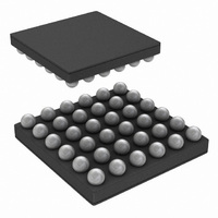
LP55281RLX/NOPB National Semiconductor, LP55281RLX/NOPB Datasheet - Page 17

LP55281RLX/NOPB
Manufacturer Part Number
LP55281RLX/NOPB
Description
IC LED DRIVER RGB 36-USMD
Manufacturer
National Semiconductor
Series
PowerWise®r
Type
RGB LED Driverr
Datasheet
1.LP55281RLNOPB.pdf
(28 pages)
Specifications of LP55281RLX/NOPB
Constant Current
Yes
Topology
PWM, Step-Up (Boost)
Number Of Outputs
12
Internal Driver
Yes
Type - Primary
Light Management Unit (LMU)
Type - Secondary
Color, RGB
Frequency
1MHz ~ 2MHz
Voltage - Supply
3 V ~ 5.5 V
Voltage - Output
4 V ~ 5.3 V
Mounting Type
Surface Mount
Package / Case
36-MicroSMDxt
Operating Temperature
-30°C ~ 85°C
Current - Output / Channel
300mA
Internal Switch(s)
Yes
Efficiency
88%
For Use With
LP55281RLEV - BOARD EVAL FOR LP5528 RGB DRIVER
Lead Free Status / RoHS Status
Lead free / RoHS Compliant
Other names
LP55281RLX
LED TEST PROCEDURE
An example of LED test sequence is presented here. Note, that user can use incremental write sequence on I
consists of the basic setup and measurement phases for all RGB LEDs and Boost voltage.
Basic setup phase for the device:
1.
2.
3.
4.
5.
6.
7.
8.
9.
10. Set the preferred value for BLUE3 (write 3Fh, 7Fh, BFh or FFh to register 08h)
11. Set the preferred value for RED4 (write 3Fh, 7Fh, BFh or FFh to register 09h)
12. Set the preferred value for GREEN4 (write 3Fh, 7Fh, BFh or FFh to register 0Ah)
13. Set the preferred value for BLUE4 (write 3Fh, 7Fh, BFh or FFh to register 0Bh)
14. Set the preferred value for ALED (write 01h - FFh to register 0Ch)
15. Dummy write: 00h to register 0Dh (Only if the incremental write sequence is used)
16. Dummy write: 00h to register 0Eh (Only if the incremental write sequence is used)
17. Set preferred boost voltage (write 00h - FFh to register 0Fh)
18. Set preferred boost frequency (write 00h - 07h to register 10h, PWM frequency can be anything)
19. Enable boost and RGB drivers (write CFh to register 11h)
20. Wait 20 ms for the device and boost startup
Measurement phase:
1.
2.
3.
4.
5.
LED TEST TIME ESTIMATION
Assuming the maximum clock frequencies used in SPI or I
compatible interfaces, the following table predicts the overall
test sequence time for the test procedure shown above. This
estimation gives the shortest time possible. Incremental write
is assumed with I
cluded.
Give reset to LP55281 (by power on, NRST pin or write any data to register 60h)
Set the preferred value for RED1 (write 3Fh, 7Fh, BFh or FFh to register 00h)
Set the preferred value for GREEN1 (write 3Fh, 7Fh, BFh or FFh to register 01h)
Set the preferred value for BLUE1 (write 3Fh, 7Fh, BFh or FFh to register 02h)
Set the preferred value for RED2 (write 3Fh, 7Fh, BFh or FFh to register 03h)
Set the preferred value for GREEN2 (write 3Fh, 7Fh, BFh or FFh to register 04h)
Set the preferred value for BLUE2 (write 3Fh, 7Fh, BFh or FFh to register 05h)
Set the preferred value for RED3 (write 3Fh, 7Fh, BFh or FFh to register 06h)
Set the preferred value for GREEN3 (write 3Fh, 7Fh, BFh or FFh to register 07h)
Enable LED test and select output (write 1xh to register 12h)
Wait for 128 µs
Read ADC output (read register 13h)
Go to step 1 of measurement phase and define next output to be measured as many times as needed
Disable LED test (write 00h to register 12h) or give reset to the device (see step 1 in basic setup phase)
2
C. Reset and LED test disable are not in-
2
C
17
14 measurements
Boost startup
Test Phase
Total Time
Setup
0.528
4.137
24.7
I
20
2
C
Time (ms)
2
C. The test sequence
0.024
1.831
21.9
www.national.com
SPI
20


