CAT9552HV6I-GT2 ON Semiconductor, CAT9552HV6I-GT2 Datasheet - Page 8
CAT9552HV6I-GT2
Manufacturer Part Number
CAT9552HV6I-GT2
Description
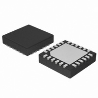
IC LED DRIVER LINEAR 24-TQFN
Manufacturer
ON Semiconductor
Type
Linear (I²C Interface)r
Datasheet
1.CAT9552YI-T2.pdf
(18 pages)
Specifications of CAT9552HV6I-GT2
Topology
PWM
Number Of Outputs
16
Internal Driver
Yes
Type - Primary
LED Blinker
Frequency
400Hz
Voltage - Supply
2.3 V ~ 5.5 V
Mounting Type
Surface Mount
Package / Case
24-TFQFN Exposed Pad
Operating Temperature
-40°C ~ 85°C
Current - Output / Channel
25mA
Internal Switch(s)
Yes
Number Of Segments
16
Low Level Output Current
25 mA
Operating Supply Voltage
2.3 V to 5.5 V
Maximum Supply Current
550 uA
Maximum Power Dissipation
1 W
Maximum Operating Temperature
+ 85 C
Mounting Style
SMD/SMT
Minimum Operating Temperature
- 40 C
Lead Free Status / RoHS Status
Lead free / RoHS Compliant
Voltage - Output
-
Efficiency
-
Lead Free Status / Rohs Status
Details


CAT9552
Acknowledge
After a successful data transfer, each receiving device
is required to generate an acknowledge. The
acknowledging device pulls down the SDA line during
the ninth clock cycle, signaling that it received the 8
bits of data. The SDA line remains stable LOW during
the HIGH period of the acknowledge related clock
pulse (Figure 4).
The CAT9552 responds with an acknowledge after
receiving a START condition and its slave address. If
the device has been selected along with a write
operation, it responds with an acknowledge after
receiving each 8- bit byte.
When the CAT9552 begins a READ mode it transmits
8 bits of data, releases the SDA line, and monitors the
line for an acknowledge. Once it receives this
acknowledge, the CAT9552 will continue to transmit
data. If no acknowledge is sent by the Master, the
device terminates data transmission and waits for a
STOP condition. The master must then issue a stop
condition to return the CAT9552 to the standby power
mode and place the device in a known state.
Registers and Bus Transactions
After the successful acknowledgement of the slave
address, the bus master will send a command byte to
the CAT9552 which will be stored in the Control
Register. The format of the Control Register is shown
in Figure 5.
Doc. No. MD-9005 Rev D
FROM TRANSMITTER
FROM RECEIVER
DATA OUTPUT
DATA OUTPUT
SCL FROM
MASTER
RESET STATE: 00h
START
Figure 4. Acknowledge Timing
0
Figure 5. Control Register
0
AUTO-INCREMENT FLAG
1
0
8
AI
The Control Register acts as a pointer to determine
which register will be written or read. The four least
significant bits, B0, B1, B2, B3, are used to select
which
to the Table 1.
If the auto increment flag is set (AI = 1), the four least
significant
automatically incremented after a read or write
operation. This allows the user to access the
CAT9552 internal registers sequentially. The content
of these bits will rollover to “0000” after the last
register is accessed.
Table 1. Internal Registers Selection
B3
0
0
0
0
0
0
0
0
1
1
B3
REGISTER ADDRESS
B2
0
0
0
0
1
1
1
1
0
0
internal
B2
B1
0
0
1
1
0
0
1
1
0
0
bits
B1
8
B0
0
1
0
1
0
1
0
1
0
1
register
of
ACKNOWLEDGE
B0
Register
Name
INPUT0
INPUT1
PSC0
PWM0
PSC1
PWM1
LS0
LS1
LS2
LS3
the
9
Characteristics subject to change without notice
is accessed,
Control
Type
READ
READ
READ/
WRITE
READ/
WRITE
READ/
WRITE
READ/
WRITE
READ/
WRITE
READ/
WRITE
READ/
WRITE
READ/
WRITE
© 2010 SCILLC. All rights reserved
Register
Register
Function
Input
Register 0
Input
Register 1
Frequency
Prescaler 0
PWM
Register 0
Frequency
Prescaler 1
PWM
Register 1
LED 0-3
Selector
LED 4-7
Selector
LED 8-11
Selector
LED 12-15
Selector
according
are
Related parts for CAT9552HV6I-GT2
Image
Part Number
Description
Manufacturer
Datasheet
Request
R

Part Number:
Description:
ON Semiconductor [VOLTAGE REGULATOR]
Manufacturer:
ON Semiconductor
Datasheet:
Part Number:
Description:
357-036-542-201 CARDEDGE 36POS DL .156 BLK LOPRO
Manufacturer:
ON Semiconductor
Datasheet:
Part Number:
Description:
357-036-542-201 CARDEDGE 36POS DL .156 BLK LOPRO
Manufacturer:
ON Semiconductor
Datasheet:
Part Number:
Description:
357-036-542-201 CARDEDGE 36POS DL .156 BLK LOPRO
Manufacturer:
ON Semiconductor
Datasheet:
Part Number:
Description:
357-036-542-201 CARDEDGE 36POS DL .156 BLK LOPRO
Manufacturer:
ON Semiconductor
Datasheet:
Part Number:
Description:
357-036-542-201 CARDEDGE 36POS DL .156 BLK LOPRO
Manufacturer:
ON Semiconductor
Datasheet:
Part Number:
Description:
357-036-542-201 CARDEDGE 36POS DL .156 BLK LOPRO
Manufacturer:
ON Semiconductor
Datasheet:
Part Number:
Description:
357-036-542-201 CARDEDGE 36POS DL .156 BLK LOPRO
Manufacturer:
ON Semiconductor
Datasheet:
Part Number:
Description:
357-036-542-201 CARDEDGE 36POS DL .156 BLK LOPRO
Manufacturer:
ON Semiconductor
Datasheet:
Part Number:
Description:
357-036-542-201 CARDEDGE 36POS DL .156 BLK LOPRO
Manufacturer:
ON Semiconductor
Datasheet:
Part Number:
Description:
357-036-542-201 CARDEDGE 36POS DL .156 BLK LOPRO
Manufacturer:
ON Semiconductor
Datasheet:
Part Number:
Description:
Manufacturer:
ON Semiconductor
Datasheet:
Part Number:
Description:
Manufacturer:
ON Semiconductor
Datasheet:
Part Number:
Description:
Manufacturer:
ON Semiconductor
Datasheet: