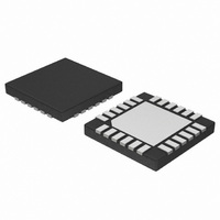
NCP5680MUTXG ON Semiconductor, NCP5680MUTXG Datasheet - Page 18

NCP5680MUTXG
Manufacturer Part Number
NCP5680MUTXG
Description
IC LED DRIVER WHT HI EFF 24-UQFN
Manufacturer
ON Semiconductor
Type
Photo Flash LED (I²C Interface)r
Datasheet
1.NCP5680MUTXG.pdf
(27 pages)
Specifications of NCP5680MUTXG
Topology
Switched Capacitor (Charge Pump)
Number Of Outputs
2
Internal Driver
No
Type - Primary
Flash/Torch
Type - Secondary
White LED
Frequency
850kHz ~ 1.15MHz
Voltage - Supply
2.7 V ~ 5.5 V
Voltage - Output
4.5 V ~ 5.3 V
Mounting Type
Surface Mount
Package / Case
24-UFQFN Exposed Pad, 24-UFQFN
Operating Temperature
-40°C ~ 85°C
Current - Output / Channel
400mA
Internal Switch(s)
Yes
Lead Free Status / RoHS Status
Lead free / RoHS Compliant
Efficiency
-
Lead Free Status / Rohs Status
Details
Available stocks
Company
Part Number
Manufacturer
Quantity
Price
Company:
Part Number:
NCP5680MUTXG
Manufacturer:
ON Semiconductor
Quantity:
2 050
Typical Sequence:
0110
0110
Select the Charge Pump Mode of Operation:
0 ³ charge pump de−activated during a flash pulse
1 ³ charge pump activated during a flash pulse
Select the Flash mode
Control a flash sequence from the I2C port:
0 ³ the I2C trigger is de−activated, clear previous sequence
1 ³ the I2C trigger is activated and the flash pulse is forced on the positive
going pulse
Control the charge pump:
0 ³ charge pump de−activated
1 ³ charge pump activated
Control the pre charge mode:
0 ³ pre charge pump de−activated
1 ³ pre charge pump activated
− send the I2C address
− setup the Output Voltage
− setup the LED1 current amplitude $03, $xx
− setup the LED1 pulse width
− setup the LED1 delay
− send the I2C address
− setup the LED2 current amplitude $04, $xx
− setup the LED2 pulse width
− setup the LED2 delay
− send the I2C address
− select the CONFIG1 register
− Activate the charge pump during a flash pulse & %0110
Activate the charge pump &
Select the flash Mode &
Clear previous sequence
− send the I2C address
− select the CONFIG1 register
− Activate the charge pump during a flash pulse & %0111
Activate the charge pump &
Select the flash Mode &
Send I2C Flash trigger
CONFIG1
$7C
$0F, $xx
$0A,$xx
$07, $xx
$7C
$0B, $xx
$08, $xx
$7C
$02
$7C
$02
http://onsemi.com
18
Figure 15. Typical Flash Pulses with 2A peak in LED2
B7
Figure 14. Typical Flash Pulses Sequence
−
−
−
−
−
1/0
B6
−
−
−
−
B5
−
1
−
−
−
1/0
B4
−
−
−
−
B3
−
−
−
−
−
1/0
B2
−
−
−
−
1/0
B1
−
−
−
−
B0
−
−
−
−
−


