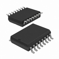
UBA2025T/N1,518 NXP Semiconductors, UBA2025T/N1,518 Datasheet - Page 10

UBA2025T/N1,518
Manufacturer Part Number
UBA2025T/N1,518
Description
IC DRIVER HALF BRIDGE 16-SOIC
Manufacturer
NXP Semiconductors
Type
CFL/TL Driverr
Specifications of UBA2025T/N1,518
Package / Case
16-SOIC (0.300", 7.5mm Width)
Frequency
42.21 ~ 44.59 kHz
Current - Supply
1.6mA
Current - Output
1.5A
Operating Temperature
-40°C ~ 150°C
Driver Type
CFL Drivers
Operating Supply Voltage
600 V
Maximum Operating Temperature
+ 150 C
Mounting Style
SMD/SMT
Maximum Output Current
1.5 A
Minimum Operating Temperature
- 40 C
Supply Current
1.6 mA
Lead Free Status / RoHS Status
Lead free / RoHS Compliant
Voltage - Supply
-
Lead Free Status / Rohs Status
Lead free / RoHS Compliant
Other names
568-4923-2
935287838518
935287838518
NXP Semiconductors
Table 6.
T
PGND; currents are positive when flowing into the IC; unless otherwise specified.
[1]
[2]
[3]
[4]
[5]
[6]
[7]
UBA2025_1
Product data sheet
Symbol
R
V
feed forward
R
I
f
f
R
R
i(RHV)
ff
ff(ratio)
amb
Fd(bs)
on(150)
i(RHV)
s
CPAV
The start-up supply current is specified in a temperature (T
the start-up supply current is < 350 A.
The clamp margin is defined as the voltage difference between turn-on of the clamp and start of oscillation. The clamp is in the off-state
at start of oscillation.
Data sampling of V
Data sampling of V
Within the allowed range of R
The input current at pin RHV may increase to 1.6 mA during voltage transient on pin VDC. Only for pin RHV currents beyond
approximately 550 mA the oscillator frequency is proportional to the pin RHV current.
The symmetry is best calculated using f
between turn-off of G2 and turn-off of G1, and the T2 total time the time between turn-off of G1 and turn-off of G2.
= 25 C; voltage on pin VS = 11 V; V
/R
on(25)
Characteristics
Parameter
on-state resistance ratio
(150 C to 25 C)
bootstrap diode forward
voltage
input resistance on pin
RHV
input current on pin RHV
feed forward frequency
feed forward frequency
ratio
series resistance
resistance on pin CPAV
th(capm)
th(capm)
is performed at the end of conduction of T2.
is performed at the start of conduction of T2.
…continued
IREF
, defined as 30 k +10%.
ff(ratio)
FS
where f
Conditions
I
during normal operation
pin RHV current = 0.75 mA
pin RHV current = 1 mA
pin RHV current = 1 mA
CPAV switch; pin CPAV current = 100 A
used with C
CPAV pin current = 10 A
FS
S1A and S1B voltage= 11 V, GLI and GLO voltage measured with respect to
= 5 mA
Rev. 01 — 16 October 2009
ff(ratio)
vj
= T1 total time divided by the T2 total time with the T1 total time the time
CPAV
) range of 0 C to 125 C. For T
for averaging;
vj
< 0 C and T
[6]
[7]
Min
-
0.6
1.54
0
60.4
80.3
0.9
0.75
22.4
vj
> 125 C
UBA2025
Typ
2.7
1.0
2.2
63.6
84.5
1.0
1.5
32
© NXP B.V. 2009. All rights reserved.
CFL power IC
Max
-
1.4
2.86
1
66.15 kHz
88.2
1.1
2.25
41.6
10 of 17
Unit
V
k
mA
kHz
k
k


