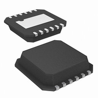
HIP2100IR4Z Intersil, HIP2100IR4Z Datasheet - Page 6

HIP2100IR4Z
Manufacturer Part Number
HIP2100IR4Z
Description
IC DRIVER HALF BRIDGE 100V 12DFN
Manufacturer
Intersil
Datasheet
1.HIP2100IBZT.pdf
(12 pages)
Specifications of HIP2100IR4Z
Configuration
Half Bridge
Input Type
PWM
Delay Time
20ns
Current - Peak
2A
Number Of Configurations
1
Number Of Outputs
2
High Side Voltage - Max (bootstrap)
114V
Voltage - Supply
9 V ~ 14 V
Operating Temperature
-40°C ~ 125°C
Mounting Type
Surface Mount
Package / Case
12-DFN
Lead Free Status / RoHS Status
Lead free / RoHS Compliant
Pin Descriptions
Timing Diagrams
Typical Performance Curves
SYMBOL
0.01
EPAD
0.1
V
V
10
HO
HB
HS
LO
FIGURE 5. OPERATING CURRENT vs FREQUENCY
HI
LI
DD
SS
HO,
1
10k
LO
HI,
LI
Positive Supply to lower gate drivers. De-couple this pin to V
High-Side Bootstrap supply. External bootstrap capacitor is required. Connect positive side of bootstrap capacitor to this pin.
Bootstrap diode is on-chip.
High-Side Output. Connect to gate of High-Side power MOSFET.
High-Side Source connection. Connect to source of High-Side power MOSFET. Connect negative side of bootstrap capacitor to
this pin.
High-Side input.
Low-Side input.
Chip negative supply, generally will be ground.
Low-Side Output. Connect to gate of Low-Side power MOSFET.
Exposed Pad. Connect to ground or float. The EPAD is electrically isolated from all other pins.
FIGURE 3.
FREQUENCY (Hz)
T = +150°C
T = +125°C
T = +25°C
T = -40°C
t
t
HPLH
6
LPLH
100k
,
t
t
HPHL
LPHL
,
1M
HIP2100
DESCRIPTION
SS
. Bootstrap diode connected to HB.
FIGURE 6. HB TO V
0.01
0.1
10
1
HO
LO
10k
HI
LI
FREQUENCY
t
MON
SS
OPERATING CURRENT vs
FIGURE 4.
FREQUENCY (Hz)
T = +150°C
T = -40°C
T = +125°C
T = +25°C
100k
t
MOFF
FN4022.14
1M


