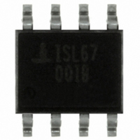
ISL6700IB Intersil, ISL6700IB Datasheet - Page 7

ISL6700IB
Manufacturer Part Number
ISL6700IB
Description
IC DRIVER HALF BRIDGE DUAL 8SOIC
Manufacturer
Intersil
Datasheet
1.ISL6700IBZ.pdf
(8 pages)
Specifications of ISL6700IB
Configuration
Half Bridge
Input Type
PWM
Delay Time
70ns
Current - Peak
1.4A
Number Of Configurations
1
Number Of Outputs
2
High Side Voltage - Max (bootstrap)
80V
Voltage - Supply
9 V ~ 15 V
Operating Temperature
-40°C ~ 125°C
Mounting Type
Surface Mount
Package / Case
8-SOIC (3.9mm Width)
Lead Free Status / RoHS Status
Contains lead / RoHS non-compliant
Available stocks
Company
Part Number
Manufacturer
Quantity
Price
Company:
Part Number:
ISL6700IBZ
Manufacturer:
Intersil
Quantity:
1 216
Company:
Part Number:
ISL6700IBZ
Manufacturer:
Intersil
Quantity:
500
Part Number:
ISL6700IBZ
Manufacturer:
INTERSIL
Quantity:
20 000
Part Number:
ISL6700IBZ-T
Manufacturer:
INTERSIL
Quantity:
20 000
Quad Flat No-Lead Plastic Package (QFN)
Micro Lead Frame Plastic Package (MLFP)
7
ISL6700
L12.4x4
12 LEAD QUAD FLAT NO-LEAD PLASTIC PACKAGE
(COMPLIANT TO JEDEC MO-220-VGGC ISSUE C)
NOTES:
10. Depending on the method of lead termination at the edge of the
1. Dimensioning and tolerancing conform to ASME Y14.5-1994.
2. N is the number of terminals.
3. Nd and Ne refer to the number of terminals on each D and E.
4. All dimensions are in millimeters. Angles are in degrees.
5. Dimension b applies to the metallized terminal and is measured
6. The configuration of the pin #1 identifier is optional, but must be
7. Dimensions D2 and E2 are for the exposed pads which provide
8. Nominal dimensions are provided to assist with PCB Land Pattern
9. Features and dimensions A2, A3, D1, E1, P & θ are present when
SYMBOL
between 0.15mm and 0.30mm from the terminal tip.
located within the zone indicated. The pin #1 identifier may be
either a mold or mark feature.
improved electrical and thermal performance.
Design efforts, see Intersil Technical Brief TB389.
Anvil singulation method is used and not present for saw
singulation.
package, a maximum 0.15mm pull back (L1) maybe present. L
minus L1 to be equal to or greater than 0.3mm.
A1
A2
A3
D1
D2
E1
E2
Nd
Ne
L1
A
D
E
N
P
b
e
k
L
θ
0.80
0.23
1.95
1.95
0.25
0.35
MIN
-
-
-
-
-
MILLIMETERS
NOMINAL
4.00 BSC
3.75 BSC
4.00 BSC
3.75 BSC
0.20 REF
0.80 BSC
0.90
0.28
2.10
2.10
0.60
12
3
3
-
-
-
-
-
-
MAX
1.00
0.05
1.00
0.38
2.25
2.25
0.75
0.15
0.60
12
-
December 29, 2004
Rev. 1 5/03
NOTES
FN9077.6
5, 8
7, 8
7, 8
10
9
9
9
9
8
2
3
3
9
9
-
-
-
-
-
-


