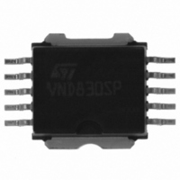
VND830SP13TR STMicroelectronics, VND830SP13TR Datasheet - Page 18

VND830SP13TR
Manufacturer Part Number
VND830SP13TR
Description
IC DRIVER 2CH HI-SIDE POWERSO-10
Manufacturer
STMicroelectronics
Type
High Sider
Datasheet
1.VND830SP13TR.pdf
(27 pages)
Specifications of VND830SP13TR
Input Type
Non-Inverting
Number Of Outputs
2
On-state Resistance
60 mOhm
Current - Peak Output
9A
Voltage - Supply
5.5 V ~ 36 V
Operating Temperature
-40°C ~ 150°C
Mounting Type
Surface Mount
Package / Case
PowerSO-10 Exposed Bottom Pad
Supply Voltage (min)
5.5 V
Supply Current
40 mA
Maximum Power Dissipation
73500 mW
Maximum Operating Temperature
+ 150 C
Mounting Style
SMD/SMT
Minimum Operating Temperature
- 40 C
Switch Type
High Side
Power Switch On Resistance
60mOhm
Output Current
9A
Package Type
PowerSO
Operating Temperature (min)
-40C
Operating Temperature (max)
150C
Operating Temperature Classification
Automotive
Mounting
Surface Mount
Pin Count
10
Lead Free Status / RoHS Status
Contains lead / RoHS non-compliant
Current - Output / Channel
-
Lead Free Status / Rohs Status
Lead free / RoHS Compliant
Other names
497-3306-2
Available stocks
Company
Part Number
Manufacturer
Quantity
Price
Company:
Part Number:
VND830SP13TR
Manufacturer:
PANASONIC
Quantity:
100
Part Number:
VND830SP13TR
Manufacturer:
ST
Quantity:
20 000
Application information
3.4
18/27
Open-load detection in off-state
Off-state open-load detection requires an external pull-up resistor (R
OUTPUT pin and a positive supply voltage (V
microprocessor.
The external resistor has to be selected according to the following requirements:
1.
2.
Because I
up resistor R
standby.
Figure 25. Open-load detection in off-state
No false open-load indication when load is connected: in this case we have to avoid
V
V
No misdetection when load is disconnected: in this case the V
V
OUT
OUT
OLmax
s(OFF)
= (V
to be higher than V
; this results in the following condition R
PU
STATUS
PU
should be connected to a supply that is switched OFF when the module is in
INPUT
may significantly increase if V
/ (R
L
+ R
PU
))R
Olmin
DRIVER
Doc ID 7380 Rev 4
LOGIC
L
+
< V
; this results in the following condition
Olmin.
GROUND
+
-
V
V
CC
OL
PU
V batt.
out
R
) like the +5V line used to supply the
is pulled high (up to several mA), the pull-
PU
< (V
OUT
PU
I
L(off2)
- V
OLmax
OUT
PU
V
PU
has to be higher than
) connected between
) / I
L(off2)
R
R
PU
L
.
VND830SP


