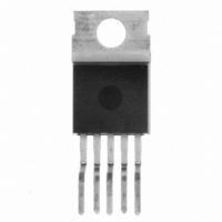
BTS410F2 Infineon Technologies, BTS410F2 Datasheet - Page 4

BTS410F2
Manufacturer Part Number
BTS410F2
Description
IC SWITCH PWR 65V TO-220AB-5
Manufacturer
Infineon Technologies
Series
PROFET®r
Type
High Sider
Specifications of BTS410F2
Input Type
Non-Inverting
Number Of Outputs
1
On-state Resistance
190 mOhm
Current - Output / Channel
1.8A
Current - Peak Output
5.5A
Voltage - Supply
4.7 V ~ 42 V
Operating Temperature
-40°C ~ 150°C
Mounting Type
Through Hole
Package / Case
TO-220AB
Switch Type
High Side
Power Switch Family
BTS 410
Input Voltage
-0.5 to 6V
Power Switch On Resistance
190mOhm
Output Current
1.6A
Mounting
Through Hole
Package Type
TO-220AB
Operating Temperature (min)
-40C
Operating Temperature (max)
150C
Operating Temperature Classification
Automotive
Pin Count
5 +Tab
Power Dissipation
50W
Lead Free Status / RoHS Status
Contains lead / RoHS non-compliant
Other names
BTS410F2
BTS410F2IN
BTS410F2NK
SP000011236
BTS410F2IN
BTS410F2NK
SP000011236
Available stocks
Company
Part Number
Manufacturer
Quantity
Price
Company:
Part Number:
BTS410F2
Manufacturer:
INF
Quantity:
5 510
Company:
Part Number:
BTS410F2E3043
Manufacturer:
INF
Quantity:
6 161
Company:
Part Number:
BTS410F2E3062A
Manufacturer:
INF
Quantity:
5 309
Protection Functions
( max 450 s if V
9
10
11
Semiconductor Group
Parameter and Conditions
at T
Initial peak short circuit current limit (pin 3 to 5)
Overload shutdown current limit
Short circuit shutdown delay after input pos. slope
Output clamp (inductive load switch off)
at V
Short circuit shutdown detection voltage(pin 3 to 5) V
Thermal overload trip temperature
Thermal hysteresis
Reverse battery (pin 3 to 1)
Diagnostic Characteristics
Open load detection current
)
) Short circuit current limit for max. duration of t
) Requires 150
min value valid only, if input "low" time exceeds 60 s
V
V
(on-condition)
ON
j
Integrated protection functions are designed to prevent IC destruction under fault conditions described in the
data sheet. Fault conditions are considered as “outside” normal operating range. Protection functions are not
designed for continuous repetitive operation.
diode has to be limited by the connected load. Note that the power dissipation is higher compared to normal
operating conditions due to the voltage drop across the intrinsic drain-source diode. The temperature
protection is not active during reverse current operation! Input and Status currents have to be limited (see
max. ratings page 2 and circuit page 7).
ON
OUT
= 25 °C, V
> V
= 8 V, T
= V
ON(SC)
bb
bb
- V
,
= 12 V unless otherwise specified
j
= T
ON(CL)
ON
resistor in GND connection. The reverse load current through the intrinsic drain-source
jt
> V
(see timing diagrams, page 11)
9
I
)
L
ON(SC)
= 40 mA, T
I
L
= 1 A, T
11
)
)
T
T
j
j
j
=-40..+150°C:
=-40..+150°C: V
=-40..+150°C:
j
=-40 ..150°C:
T
j
T
=+150°C:
d(SC) max
T
j
j
=-40°C:
=25°C:
4
10
)
,
=450 s, prior to shutdown
I
I
t
T
-V
I
Symbol
L(SCp)
L(SCr)
d(SC)
L (OL)
jt
T
ON(CL)
ON(SC)
bb
jt
150
min
4.0
3.5
2.0
61
--
--
--
--
--
--
2
Values
5.5
3.5
2.7
8.5
typ
68
10
--
--
--
--
--
--
BTS 410 F2
max
450
150
7.5
2003-Oct-01
11
10
73
75
32
--
--
--
--
Unit
mA
°C
A
A
V
V
K
V
s


