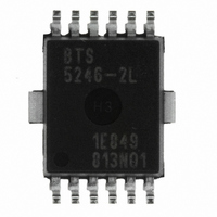
BTS5246-2L Infineon Technologies, BTS5246-2L Datasheet - Page 9

BTS5246-2L
Manufacturer Part Number
BTS5246-2L
Description
IC PWR SWITCH HISIDE PG-DSO-12-9
Manufacturer
Infineon Technologies
Type
High Sider
Datasheet
1.BTS5246-2L.pdf
(24 pages)
Specifications of BTS5246-2L
Package / Case
DSO-12
Input Type
Non-Inverting
Number Of Outputs
2
On-state Resistance
35 mOhm
Current - Output / Channel
6.3A
Current - Peak Output
50A
Voltage - Supply
4.5 V ~ 28 V
Operating Temperature
-40°C ~ 150°C
Mounting Type
Surface Mount
On Resistance (max)
0.035 Ohms
Maximum Operating Temperature
+ 150 C
Minimum Operating Temperature
- 40 C
Maximum Power Dissipation
1400 mW
Mounting Style
SMD/SMT
Supply Current
3.2 mA
Lead Free Status / RoHS Status
Lead free / RoHS Compliant
Lead Free Status / RoHS Status
Lead free / RoHS Compliant, Lead free / RoHS Compliant
Other names
BTS5246-2LINTR
BTS52462LXT
SP000281083
BTS52462LXT
SP000281083
Available stocks
Company
Part Number
Manufacturer
Quantity
Price
Part Number:
BTS5246-2L
Manufacturer:
INFINEON/英飞凌
Quantity:
20 000
1) R and L describe the complete circuit impedance including line, contact and generator impedances
2) Load Dump is specified in ISO 7637, R
3) Current limitation is a protection feature. Operation in current limitation is considered as “outside” normal operating range.
4) Pulse shape represents inductive switch off: I
5) Device mounted on PCB (50 mm x 50 mm x 1.5 mm epoxy, FR4) with 6 cm
Note: Stresses above the ones listed here may cause permanent damage to the device. Exposure to absolute
Note: Integrated protection functions are designed to prevent IC destruction under fault conditions described in the
Data Sheet
Protection features are not designed for continuous repetitive operation.
thick) for V
maximum rating conditions for extended periods may affect device reliability.
data sheet. Fault conditions are considered as “outside” normal operating range. Protection functions are
not designed for continuous repetitive operation.
bb
connection. PCB is vertical without blown air.
I
is the internal resistance of the Load Dump pulse generator
L
(t) = I
L
(0) * (1 - t
9
/
t
peak
); 0 < t < t
2
peak.
Smart High-Side Power Switch
copper heatsinking area (one layer, 70 µm
Please see
Electrical Characteristics
Figure 8
Rev.1.4, 2008-09-01
BTS5246-2L


