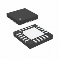
LT3572EUF#PBF Linear Technology, LT3572EUF#PBF Datasheet

LT3572EUF#PBF
Specifications of LT3572EUF#PBF
Available stocks
Related parts for LT3572EUF#PBF
LT3572EUF#PBF Summary of contents
Page 1
... Piezo drivers are allowed to start switching. The LT3572 is available in a (4mm × 4mm) 20-pin QFN package. , LT, LTC and LTM are registered trademarks of Linear Technology Corporation. All other trademarks are the property of their respective owners. V OUT ...
Page 2
... Storage Temperature Range ................... –65°C to 125°C ORDER INFORMATION LEAD FREE FINISH TAPE AND REEL LT3572EUF#PBF LT3572EUF#TRPBF Consult LTC Marketing for parts specifi ed with wider operating temperature ranges. Consult LTC Marketing for information on non-standard lead based fi nish parts. For more information on lead free part marking, go to: For more information on tape and reel specifi ...
Page 3
ELECTRICAL CHARACTERISTICS temperature range, otherwise specifi cations are at T PARAMETER PWMA Pin Threshold PWMB Pin Threshold PGOOD Rising Threshold PGOOD Falling Threshold PGOOD Resistance Switching Frequency Maximum Duty Cycle Synchronization Frequency SYNC Pin Thresholds SS Current FB Pin Voltage ...
Page 4
LT3572 TYPICAL PERFORMANCE CHARACTERISTICS Feedback Pin Voltage vs Temperature 1.25 1.24 1.23 1.22 1.21 1.20 – –25 0 100 125 TEMPERATURE (°C) 3572 G01 Quiescent Current vs Temperature 4.0 3.5 3.0 2.5 2.0 1.5 1.0 0.5 0 ...
Page 5
PIN FUNCTIONS SW (Pin 1): Switch Node. This pin connects to the col- lector of an internal NPN power switch. V (Pin 2): Input Supply Pin. This pin must be locally IN bypassed with a capacitor. SYNC (Pin 3): Synchronization ...
Page 6
LT3572 BLOCK DIAGRAM PWMA OUT Q2 OUTA OUTA OUTB OSCILLATOR OUTB 16 Q9 PWMB SHDN START-UP/ A6 INTERNAL BIAS ...
Page 7
OPERATION Switching Regulator The LT3572 uses a constant frequency, current mode, control scheme to provide excellent line and load regulation for the output drivers. Operation can be best understood by referring to the Block Diagram in Figure 1. A pulse ...
Page 8
LT3572 APPLICATIONS INFORMATION Duty Cycle The typical maximum duty cycle of the LT3572 is 95% at 1MHz. This maximum duty cycle reduces as the switch- ing frequency is increased. The duty cycle for a given application is given by: + ...
Page 9
APPLICATIONS INFORMATION PWM The LT3572 can PWM the output drivers at a very high frequency. The limitation on the frequency is determined by the internal rise in die temperature that occurs when driving the motor. The power delivered to the ...
Page 10
LT3572 APPLICATIONS INFORMATION of several ceramic capacitor manufacturers. Consult the manufacturers for detailed information on their entire selection of ceramic parts. Table 2. Ceramic Capacitor Manufacturers Taiyo Yuden (408) 573-4150 AVX (803) 448-9411 Murata (714) 852-2001 Diode Selection A Schottky ...
Page 11
... ON THE TOP AND BOTTOM OF PACKAGE Information furnished by Linear Technology Corporation is believed to be accurate and reliable. However, no responsibility is assumed for its use. Linear Technology Corporation makes no representa- tion that the interconnection of its circuits as described herein will not infringe on existing patent rights. UF Package 20-Lead Plastic QFN (4mm × ...
Page 12
... DFN8 and MS8E Packages www.linear.com ● = 60V, 24-Lead SO Package OUT(MAX) = 35V Maximum, 40mA Current Limit for OUT = 40V Analog/PWM, I < 1μA, OUT(MAX 40V 1mA, I < 1μA, OUT(MAX 3572fa LT 0408 REV A • PRINTED IN USA © LINEAR TECHNOLOGY CORPORATION 2007 ...


