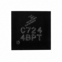
MPC17C724EP Freescale Semiconductor, MPC17C724EP Datasheet - Page 7

MPC17C724EP
Manufacturer Part Number
MPC17C724EP
Description
IC MOTOR DRVR H-BRDG DUAL 16-QFN
Manufacturer
Freescale Semiconductor
Type
Dual Half Bridge Motor Driverr
Datasheet
1.MPC17C724EP.pdf
(13 pages)
Specifications of MPC17C724EP
Applications
DC Motor Driver, Stepper Motor Driver, H Bridge
Number Of Outputs
1
Current - Output
400mA
Voltage - Load
2.7 V ~ 5.5 V
Voltage - Supply
2.7 V ~ 5.5 V
Operating Temperature
-20°C ~ 85°C
Mounting Type
Surface Mount
Package / Case
16-QFN
Operating Supply Voltage
3 V
Supply Current
0.04 mA
Mounting Style
SMD/SMT
For Use With
KIT17C724EPEVBE - KIT FOR 17C7242CH HBRIDGE PWR IC
Lead Free Status / RoHS Status
Lead free / RoHS Compliant
Available stocks
Company
Part Number
Manufacturer
Quantity
Price
Company:
Part Number:
MPC17C724EP/R2
Manufacturer:
TI
Quantity:
3 123
Company:
Part Number:
MPC17C724EPR2
Manufacturer:
GMT
Quantity:
2 046
Part Number:
MPC17C724EPR2
Manufacturer:
FREESCALE
Quantity:
20 000
Analog Integrated Circuit Device Data
Freescale Semiconductor
Notes
H : High
L : Low
Z : High impedance
X : Don’t care
IN1,
IN2,
PSAVE
OUTA,
OUTB
19.
20.
PSAVE
Terminal 13 (PSAVE) is pulled up by an internal resistor.
When V
low-voltage shutdown detection circuit is disabled.
H
L
L
L
L
(19)
Figure 4. t
DD
t
PLH
is lower than V
PLH
50%
INPUT
and t
IN1A
IN2A
H
H
DD
X
L
L
90%
10%
DET while V
PHL
Timing
M
t
PHL
is applied, output becomes “Z” (high impedance); however, when PSAVE = “H”, the
TIMING DIAGRAMS
IN1B
IN2B
H
H
L
L
X
Table 5. Truth Table
V
OUT1A
OUT2A
DD
1.0 V
H
L
L
Z
Z
I
M
Figure 5. Low-Voltage Detection Timing
V
DD
OUTPUT
DETon
t
V
DD
DET
OUT1B
OUT2B
2.5 V
50%
H
Z
Z
L
L
90%
V
DD
TIMING DIAGRAMS
DEToff
t
V
V
DD
Disabled
Enabled
Enabled
Enabled
Enabled
DD
DET
DET
(20)
0%
(<1.0 µA)
17C724
7


