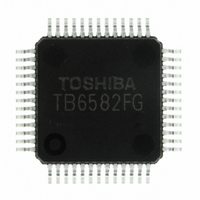
TB6582FG(O,EL) Toshiba, TB6582FG(O,EL) Datasheet - Page 14

TB6582FG(O,EL)
Manufacturer Part Number
TB6582FG(O,EL)
Description
IC BRUSHLESS MOTOR CTLR 52-QFP
Manufacturer
Toshiba
Type
3 Phase Full Wave Brushless Motor Controllerr
Datasheet
1.TB6582FGOEL.pdf
(28 pages)
Specifications of TB6582FG(O,EL)
Applications
DC Motor Controller, Brushless (BLDC), 3 Phase
Number Of Outputs
1
Voltage - Supply
6.5 V ~ 16.5 V
Operating Temperature
-30°C ~ 115°C
Mounting Type
Surface Mount
Package / Case
52-QFP
Product
Fan / Motor Controllers / Drivers
Operating Supply Voltage
15 V
Supply Current
16 mA
Mounting Style
SMD/SMT
Lead Free Status / RoHS Status
Lead free / RoHS Compliant
Current - Output
-
Voltage - Load
-
Lead Free Status / Rohs Status
Lead free / RoHS Compliant
Other names
TB6582FG(O,EL)
TB6582FGOELTR
TB6582FGOELTR
Available stocks
Company
Part Number
Manufacturer
Quantity
Price
7. Induced Voltage Detection
(Square-wave generation)
(Sine-wave generation)
The induced voltages of each phase are detected by applying an analog calculation to the current signal
generated in section 6 and the voltage signal detected at the motor.
A square wave for startup-operation control performs a control function by detecting the 60° commutation
time using the induced voltage that is generated while the motor is not commutating.
The square-wave drive operates until the phase-current frequency reaches 6 Hz (90 rpm for an 8-pole
motor).
V
V
V
V
Phase voltage equation
Eu = (Vu − Vn) − L × dIu/dt – R × Iu
<Determining the time constant of a motor >
V
V
V
V
V
wo
uo
vo
w
n
u
n
n
v
I
I
Cu
Uin
Uo
detection
Current
+
−
+
−
+
−
51
52
1
Ew
Eu
Ev
C
2
Induced voltage
C
R
L
R
L
R
L
R
1
7
detection
dIu
dIu
dIu
dt
dt
dt
R
6
+
−
+
−
+
−
Note: Under normal operation, the FRCDRV pin voltage must be 2.5 V, or the pin
To complete the phase voltage equation, values of external C
determined experimentally.
It can be achieved by setting the FRCDRV pin High (5 V) or Low (0 V).
The recommended capacitor value for C2 is the range of about 0.01 µF to 0.047
µF. However, it should be adjusted according to noise conditions.
• When FRCDRV goes Low, the current frequency signal of 0.5 Hz is generated
• When FRCDRV goes High, the current frequency signal of 30 Hz is generated
Design Specifications
−
−
−
at the drive output.
At this time, a resistor value of R
voltage constant at 2.5 V.
at the drive output.
At this time, values of a capacitor C
as to keep the Cu voltage constant at 2.5 V.
−
−
−
Ew
must be left open.
Eu
Ev
Motor equivalent circuit
control
Phase
Voltage forming
LdIu/d
RIu
Eu
Vu
Vn
14
Voltage instruction
(current limit)
Vw
Vu
Vv
6
PWM
must be determined so as to keep the Cu
1
and a resistor R
IPD
Vw
Vu
Vv
Iw
Iu
Iv
Preliminary
7
must be determined so
Vwo
Vuo
Vvo
1
, R
6
and R
Vn
TB6582FG
7
are
2007-10-18


