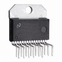
LMD18245T/NOPB National Semiconductor, LMD18245T/NOPB Datasheet - Page 17

LMD18245T/NOPB
Manufacturer Part Number
LMD18245T/NOPB
Description
IC H BRIDGE 3A 55V TO-220
Manufacturer
National Semiconductor
Datasheet
1.LMD18245TNOPB.pdf
(21 pages)
Specifications of LMD18245T/NOPB
Applications
DC Motor Driver, Stepper Motor Driver, H Bridge
Number Of Outputs
1
Current - Output
3A
Voltage - Supply
12 V ~ 55 V
Operating Temperature
-40°C ~ 125°C
Mounting Type
Through Hole
Package / Case
TO-220-15 (Bent and Staggered Leads)
Operating Temperature Classification
Automotive
Package Type
TO-220
Operating Supply Voltage (min)
12V
Operating Supply Voltage (max)
55V
Lead Free Status / RoHS Status
Lead free / RoHS Compliant
Voltage - Load
-
Lead Free Status / Rohs Status
Compliant
Other names
*LMD18245T
*LMD18245T/NOPB
LMD18245T
*LMD18245T/NOPB
LMD18245T
Available stocks
Company
Part Number
Manufacturer
Quantity
Price
Company:
Part Number:
LMD18245T/NOPB
Manufacturer:
ST
Quantity:
14 300
Part Number:
LMD18245T/NOPB
Manufacturer:
NS/国半
Quantity:
20 000
The Typical Application
HALF STEP DRIVE WITH TORQUE COMPENSATION
To make the motor take half steps, the windings can also be
energized with sinusoidal currents (Figure 12). Controlling
the winding currents in the fashion shown doubles the step
resolution without the significant torque ripple of the prior
drive technique. The motor takes one half step each time the
level of either winding current changes. Half step drive with
torque compensation is microstepping drive. Along with the
obvious advantage of increased step resolution, micro-
stepping reduces both full step oscillations and resonances
that occur as the motor and load combination is driven at its
Top Trace: Phase A Winding Current at 1A/div
Bottom Trace: Phase B Winding Current at 1A/div
Horizontal: 2 ms/div
*500 steps/second
BRAKE A = BRAKE B = 0
FIGURE 12. Winding Currents and Digital Control Signals for Half Step Drive with Torque Compensation
90˚ ELECTRICAL/FULL STEP ÷ 2 MICROSTEPS/FULL STEP = 45˚ ELECTRICAL/MICROSTEP
(Continued)
17
natural resonant frequency or subharmonics thereof. Both of
these advantages are obtained by replacing full steps with
bursts of microsteps. When compared to full step drive, the
motor runs smoother and quieter.
Figure 13 shows the lookup table for this application of the
typical application circuit. Dividing 90˚electrical per full step
by two microsteps per full step yields 45˚ electrical per
microstep.
ments of 45˚. Each full 360˚ cycle comprises eight half steps.
Rounding |cos | to four bits gives D A, the decimal equiva-
lent of the binary number applied at M4 A through M1 A.
DIRECTION A controls the polarity of the current in winding
A. Figure 12 shows the sinusoidal winding currents.
, therefore, increases from 0 to 315˚ in incre-
01187824
www.national.com
01187844


