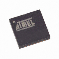
ATA6830-PKH Atmel, ATA6830-PKH Datasheet - Page 7

ATA6830-PKH
Manufacturer Part Number
ATA6830-PKH
Description
IC DRIVER MOTOR STEPPER 28-QFN
Manufacturer
Atmel
Datasheet
1.ATA6830-PKH.pdf
(23 pages)
Specifications of ATA6830-PKH
Applications
Stepper Motor Driver
Number Of Outputs
1
Current - Output
1.1A
Voltage - Supply
7 V ~ 20 V
Operating Temperature
-40°C ~ 105°C
Mounting Type
Surface Mount
Lead Free Status / RoHS Status
Contains lead / RoHS non-compliant
Package / Case
-
Voltage - Load
-
Other names
ATA6830-PKHTR
4575C–BCD–05/03
Figure 6. Synchronization Sequence
Between two commands a pause has to be included. This is necessary for a clear rec-
ogition of a new message frame (command). Figure 7 shows the timing diagram of two
commands.
Figure 7. Message Frame and Space
Every command consists of 16 bits. They will be sent with two bytes. Figure 8 shows the
message frame. The high byte is sent first, immediately followed by the low byte. Every
byte starts with a start bit and ends with a parity bit and a stop bit. The first start bit (level
0) after a pause (level 1) indicates the beginning of a new message frame. The value of
the parity bit has to be odd, i.e., the crossfooting of the byte including the parity bit is
odd. If a data packet is not recognized due to a transmission error (parity error), the
entire command is rejected.
Figure 8. Command Bits
START
START
BIT
BIT
HIGH BYTE LOW BYTE
MESSAGE FRAME
7
6
5
8 DATA
HIGH BYTE
4
BITS
3
2
1
SYNCHRONIZATION PATTERN
0
PARITY
PARITY
MESSAGE FRAME
BIT
BIT
STOP
STOP
SPACE
BIT
BIT
START
START
BIT
BIT
7
6
5
8 DATA
LOW BYTE
4
BITS
3
2
1
ATA6830
0
PARITY
PARITY
BIT
BIT
STOP
STOP
BIT
BIT
7


