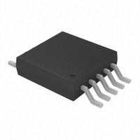
TC665EUN Microchip Technology, TC665EUN Datasheet - Page 3

TC665EUN
Manufacturer Part Number
TC665EUN
Description
IC PWM FAN SPEED CTRLR 10-MSOP
Manufacturer
Microchip Technology
Type
Controller - SMBus Fan Speedr
Datasheet
1.TC664EUN.pdf
(36 pages)
Specifications of TC665EUN
Applications
Fan Controller, Brushless (BLDC)
Number Of Outputs
1
Voltage - Supply
3 V ~ 5.5 V
Operating Temperature
-40°C ~ 85°C
Mounting Type
Surface Mount
Package / Case
10-MSOP, Micro10™, 10-uMAX, 10-uSOP
Motor Type
PWM
No. Of Outputs
1
Output Current
5mA
Output Voltage
4.4V
Supply Voltage Range
3V To 5.5V
Driver Case Style
MSOP
No. Of Pins
10
Operating Temperature Range
-40°C To +85°C
Product
Fan / Motor Controllers / Drivers
Operating Supply Voltage
3 V to 5.5 V
Supply Current
300 uA
Mounting Style
SMD/SMT
Rohs Compliant
Yes
Lead Free Status / RoHS Status
Lead free / RoHS Compliant
Current - Output
-
Voltage - Load
-
Lead Free Status / Rohs Status
Lead free / RoHS Compliant
Available stocks
Company
Part Number
Manufacturer
Quantity
Price
Company:
Part Number:
TC665EUN
Manufacturer:
Microchip Technology
Quantity:
939
Company:
Part Number:
TC665EUN
Manufacturer:
MICROCHIP
Quantity:
12 000
Company:
Part Number:
TC665EUNTR
Manufacturer:
MICROCHIP
Quantity:
12 000
1.0
Absolute Maximum Ratings *
V
Input Voltages .................................... -0.3 V to (V
Output Voltages ................................. -0.3 V to (V
Storage temperature .....................................-65°C to +150°C
Ambient temp. with power applied ................-40°C to +125°C
Maximum Junction Temperature, T
ESD protection on all pins
*Notice: Stresses above those listed under “Maximum rat-
ings” may cause permanent damage to the device. This is a
stress rating only and functional operation of the device at
those or any other conditions above those indicated in the
operational listings of this specification is not implied. Expo-
sure to maximum rating conditions for extended periods may
affect device reliability.
ELECTRICAL SPECIFICATIONS
Electrical Characteristics: Unless otherwise noted, all limits are specified for V
Supply Voltage
Operating Supply Current
Shutdown Mode Supply Current
V
V
V
Sink Current at V
Source Current at V
PWM Frequency
V
V
V
V
V
SENSE Input
SENSE Input Threshold Voltage with
Respect to GND
FAULT Output
FAULT Output LOW Voltage
FAULT Output Response Time
Fan RPM-to-Digital Output
Fan RPM ERROR
2-Wire Serial Bus Interface
Logic Input High
Logic Input Low
Logic Output Low
Input Capacitance SDA, SCLK
I/O Leakage Current
SDA Output Low Current
Note 1: Not production tested, ensured by design, tested during characterization.
DD
OUT
OUT
OUT
IN
IN
C(MAX)
IN
IN
2002 Microchip Technology Inc.
..................................................................................6.5 V
Input
Input Voltage for 100% PWM duty-cycle
Input Resistance
Input Leakage Current
PWM Output
Rise Time
Fall Time
2: For 5.0 V < V
- V
ELECTRICAL
CHARACTERISTICS
C(MIN)
Parameters
OUT
OUT
Output
Output
DD
5.5 V, the limit for V
J
............................. 150°C
V
V
I
V
DDSHDN
THSENSE
I
CRANGE
t
OLSDA
I
C(MAX)
FAULT
Sym
DD
DD
V
V
V
LEAK
I
I
V
C
I
V
I
DD
t
t
OL
OH
F
DD
IN
R
OL
OL
F
IH
IL
IN
+ 0.3 V)
+ 0.3 V)
IH
4 kV
= 2.2 V.
2.45
1.25
Min
-1.0
-1.0
3.0
1.0
5.0
-15
2.1
26
80
—
—
—
—
—
—
—
—
—
—
6
PIN FUNCTION TABLE
V
C
SCLK
SDA
GND
FAULT
NC
SENSE
V
V
10M
Typ
150
100
2.6
1.4
2.4
30
10
—
—
—
—
—
—
—
—
—
—
—
—
—
IN
OUT
DD
F
5
Name
DD
= 3.0 V to 5.5 V, -40°C <T
Max
2.75
1.55
+1.0
+1.0
300
120
+15
5.5
0.3
0.8
0.4
10
50
50
34
15
—
—
—
—
—
—
Analog Input
Analog Output
Serial Clock Input
Serial Data In/Out (Open Drain)
Ground
Digital (Open Drain) Output
No Connection
Analog Input
Digital Output
Power Supply Input
TC664/TC665
Units
µsec
µsec
mA
mA
mV
sec
mA
µA
µA
Hz
µA
µA
pF
%
V
V
V
V
V
V
V
Pins 8, 9 Open
Pins 8, 9 Open
I
I
V
V
C
V
I
RPM > 1600
Note 2
I
Note 1
V
OH
OL
OL
OL
Function
OL
OH
F
DD
OL
= 1 µF
= 1 mA, Note 1
= 2.5 mA
= 3 mA
= 5 mA, Note 1
= 10% of V
= 0.6 V
= 80% of V
= 5.0 V
A
Conditions
< +85°C.
DS21737A-page 3
DD
DD


