TC665EUN Microchip Technology, TC665EUN Datasheet - Page 4
TC665EUN
Manufacturer Part Number
TC665EUN
Description
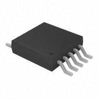
IC PWM FAN SPEED CTRLR 10-MSOP
Manufacturer
Microchip Technology
Type
Controller - SMBus Fan Speedr
Datasheet
1.TC664EUN.pdf
(36 pages)
Specifications of TC665EUN
Applications
Fan Controller, Brushless (BLDC)
Number Of Outputs
1
Voltage - Supply
3 V ~ 5.5 V
Operating Temperature
-40°C ~ 85°C
Mounting Type
Surface Mount
Package / Case
10-MSOP, Micro10™, 10-uMAX, 10-uSOP
Motor Type
PWM
No. Of Outputs
1
Output Current
5mA
Output Voltage
4.4V
Supply Voltage Range
3V To 5.5V
Driver Case Style
MSOP
No. Of Pins
10
Operating Temperature Range
-40°C To +85°C
Product
Fan / Motor Controllers / Drivers
Operating Supply Voltage
3 V to 5.5 V
Supply Current
300 uA
Mounting Style
SMD/SMT
Rohs Compliant
Yes
Lead Free Status / RoHS Status
Lead free / RoHS Compliant
Current - Output
-
Voltage - Load
-
Lead Free Status / Rohs Status
Lead free / RoHS Compliant
Available stocks
Company
Part Number
Manufacturer
Quantity
Price
Company:

Part Number:
TC665EUN
Manufacturer:
Microchip Technology
Quantity:
939
Company:
Part Number:
TC665EUN
Manufacturer:
MICROCHIP
Quantity:
12 000
Company:
Part Number:
TC665EUNTR
Manufacturer:
MICROCHIP
Quantity:
12 000


TC664/TC665
TEMPERATURE SPECIFICATIONS
TIMING SPECIFICATIONS
DS21737A-page 4
Electrical Characteristics: Unless otherwise noted, all parameters apply at V
Temperature Ranges:
Specified Temperature Range
Operating Temperature Range
Storage Temperature Range
Thermal Package Resistances:
Thermal Resistance, 10 Pin MSOP
Electrical Characteristics: Unless otherwise noted, all limits are specified for V
-40°C <T
SMBus Interface (See Figure 1-1)
Serial Port Frequency
Low Clock Period
High Clock Period
SCLK and SDA Rise Time
SCLK and SDA Fall Time
Start Condition Setup Time
SCLK Clock Period Time
Start Condition Hold Time
Data in SetupTime to SCLK
High
Data in Hold Time after SCLK
Low
Stop Condition Setup Time
Bus Free Time Prior to New
Transition
Note 1: Not production tested, ensured by design, tested during characterization.
2: Time the bus must be free before a new transmission can start.
A
Parameters
< +85°C
Parameters
t
t
SU(START)
t
t
SU(STOP)
H(START)
SU-DATA
t
H-DATA
t
Sym
t
t
HIGH
LOW
IDLE
f
t
SC
t
SC
t
R
F
Symbol
T
T
T
JA
A
A
A
Min
250
300
4.7
4.7
4.7
4.0
4.0
4.7
10
—
—
0
Min
-40
-40
-65
—
Typ
—
—
—
—
—
—
—
—
—
—
—
—
Typ
113
—
—
—
1000
Max
100
300
—
—
—
—
—
—
—
—
+125
+150
Max
+85
—
Units
µsec Note 1
µsec Note 1
nsec Note 1
nsec Note 1
µsec Note 1
µsec Note 1
µsec Note 1
nsec Note 1
nsec Note 1
µsec Note 1
µsec Note 1 and Note 2
kHz
DD
DD
= 3.0 V to 5.5 V
= 3.0 V to 5.5 V,
Note 1
Units
°C/W
°C
°C
°C
2002 Microchip Technology Inc.
Conditions
Conditions
Related parts for TC665EUN
Image
Part Number
Description
Manufacturer
Datasheet
Request
R

Part Number:
Description:
Smbus Pwm Fan Speed Controllers With Fan Fault Detection
Manufacturer:
Microchip Technology Inc.
Datasheet:
Part Number:
Description:
Manufacturer:
Microchip Technology Inc.
Datasheet:
Part Number:
Description:
Manufacturer:
Microchip Technology Inc.
Datasheet:
Part Number:
Description:
Manufacturer:
Microchip Technology Inc.
Datasheet:
Part Number:
Description:
Manufacturer:
Microchip Technology Inc.
Datasheet:
Part Number:
Description:
Manufacturer:
Microchip Technology Inc.
Datasheet:
Part Number:
Description:
Manufacturer:
Microchip Technology Inc.
Datasheet:
Part Number:
Description:
Manufacturer:
Microchip Technology Inc.
Datasheet:
Part Number:
Description:
Manufacturer:
Microchip Technology Inc.
Datasheet: