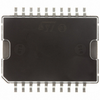
E-L9935013TR STMicroelectronics, E-L9935013TR Datasheet - Page 13

E-L9935013TR
Manufacturer Part Number
E-L9935013TR
Description
IC STEPPER MOTOR DVR 2PH 20PWRSO
Manufacturer
STMicroelectronics
Type
2 Phase Stepper Motor Driverr
Datasheet
1.L9935.pdf
(29 pages)
Specifications of E-L9935013TR
Applications
Stepper Motor Driver, 2 Phase
Number Of Outputs
1
Current - Output
±1.2A
Voltage - Supply
8 V ~ 24 V
Operating Temperature
-40°C ~ 150°C
Mounting Type
Surface Mount
Package / Case
PowerSO-20 Exposed Bottom Pad
Product
Stepper Motor Controllers / Drivers
Operating Supply Voltage
14.4 V
Supply Current
4.5 mA
Mounting Style
SMD/SMT
Lead Free Status / RoHS Status
Lead free / RoHS Compliant
Voltage - Load
-
Lead Free Status / Rohs Status
Lead free / RoHS Compliant
Other names
497-10346-2
E-L9935013TR
E-L9935013TR
Available stocks
Company
Part Number
Manufacturer
Quantity
Price
L9935
5.2
5.2.1
5.2.2
5.2.3
Full bridge function
Figure 5.
No current
Bit 5, bit 4 (corresponding bit 2 and bit1 for bridge B) both are HIGH, the current logic will
inhibit all drivers D
signal of the current sense comparator comp 1.
Turning on
Changing bit 5 or bit 4 or both to LOW will turn on either M
(depending on the phase signal bit 3). Current will start to flow through the load. The current
will be sensed by the drop across R
The threshold of the comparator comp 1 depends on the current settings of bit 5 and bit 4.
The current will rise until it exceeds the turn off threshold of comp 1.
Chopping
Exceeding the threshold of comp 1 the drive logic will turn off the sink transistor (M
M
turning on M
switch over spikes caused by capacitive load components up to 5 nF.
Turning off for example M
wheeling current flows through M
This leads to a slow current decay during flyback. Maximum duty cycles of more than 85%
(at f
shown in
22
). The sink transistor periodically is turned on again by the oscillator. Immediately after
OSC
= 25 kHz) are possible. In this case current flows of both bridges will overlap (not
Figure
12
Displays a full bridge including the current sense circuit.
or M
7).
11
22
, D
the comparator comp 1 will be inhibited for a certain time to blank
12
, D
12
will yield a flyback current through D
21
, D
Doc ID 5198 Rev 9
22
21
, the load and D
1
turning off M
.
11
, M
11
).
12
, M
11
21
, M
and M
22
11
. (So now the free
independently from the
Functional description
22
or M
21
and M
12
12
or
13/29


