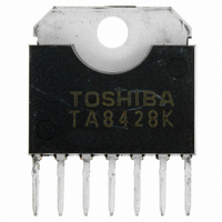
TA8428K(O,S) Toshiba, TA8428K(O,S) Datasheet

TA8428K(O,S)
Specifications of TA8428K(O,S)
TA8428K(5,S)
TA8428K(O,S)
TA8428K5S
TA8428K5S
TA8428KOS
Related parts for TA8428K(O,S)
TA8428K(O,S) Summary of contents
Page 1
... TOSHIBA BIPOLAR LINEAR INTEGRATED CIRCUIT SILICON MONOLITHIC TA8428K(S), TA8428F/FG FULL BRIDGE DRIVER The TA8428K (S), TA8428F/FG is Full Bridge Driver IC for Brush Motor Rotation Control. Forward Rotation, Reverse Rotation, Stop and Braking operations are available. Thermal Shutdown and Short Current Protector are provided. ...
Page 2
BLOCK DIAGRAM PIN FUNCTION PIN No. SYMBOL K(S) F/ OUTA 4 Fin GND 5 16 OUT A 6 Other pin TA8428K (S), TA8428F/FG has 2 build−in ...
Page 3
Short current protector (ISD) Short current protector circuit senses all output transistor current. If output transistor current is over the specified limiting current value (2.0~3.0 A Typ.), short current protector operates and all output transistors periodically turn “OFF” (High Impedance ...
Page 4
INTERNAL CIRCUIT TA8428K(S)/F/FG 4 TA8428K(S) TA8428F/FG 2007-6-4 ...
Page 5
ABSOLUTE MAXIMUM RATINGS CHARACTERISTIC Supply Voltage Input Voltage PEAK K (S) type AVE. Output Current PEAK F/FG type AVE. K (S) type Power Dissipation F/FG type Operating Temperature Storage Temperature Note 100 ms Note 2: No heat ...
Page 6
FUNCTION INPUT IN1 IN2 TEST CIRCUIT CC1 CC2 CC3 TEST CIRCUIT ...
Page 7
TEST CIRCUIT TEST CIRCUIT TA8428K(S),F/FG TA8428K(S),F/FG 7 TA8428K(S)/F/FG TA8428K(S) TA8428F/FG 2007-6-4 ...
Page 8
TA8428F/FG TA8428K(S)/F/FG TA8428F/FG 8 2007-6-4 ...
Page 9
APPLICATION CIRCUIT Recommend to take approximately 100 μs of input dead time for reliable operations. Note: Note: Utmost care is necessary in the design of the output short-circuiting between outputs, air contamination faults, or faults due to improper ...
Page 10
PACKAGE DIMENSIONS HSIP7−P−2.54 Weight : 1.88 g (Typ.) TA8428K(S)/F/FG 10 Unit : mm 2007-6-4 ...
Page 11
PACKAGE DIMENSIONS HSOP20−P−450−1.00 Weight : 0.79 g (Typ.) TA8428K(S)/F/FG 11 Unit : mm 2007-6-4 ...
Page 12
... Application Circuits The application circuits shown in this document are provided for reference purposes only. Thorough evaluation is required, especially at the mass production design stage. Toshiba does not grant any license to any industrial property rights by providing these examples of application circuits. 5. Test Circuits Components in the test circuits are used only to obtain and confirm the device characteristics. These components and circuits are not guaranteed to prevent malfunction or failure from occurring in the application equipment ...
Page 13
Points to remember on handling of ICs (1) Over current Protection Circuit Over current protection circuits (referred to as current limiter circuits) do not necessarily protect ICs under all circumstances. If the Over current protection circuits operate against the over ...
Page 14
... The information contained herein is presented only as a guide for the applications of our products. No responsibility is assumed by TOSHIBA for any infringements of patents or other rights of the third parties which may result from its use. No license is granted by implication or otherwise under any patents or other rights of TOSHIBA or the third parties ...


