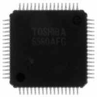
TB6560AFG(O) Toshiba, TB6560AFG(O) Datasheet - Page 3

TB6560AFG(O)
Manufacturer Part Number
TB6560AFG(O)
Description
IC STEPPER MOTOR DRVR 2PH 64HQFP
Manufacturer
Toshiba
Type
Stepper Motor Driverr
Specifications of TB6560AFG(O)
Applications
Stepper Motor Driver, 2 Phase
Number Of Outputs
1
Current - Output
1.5A
Voltage - Load
4.5 V ~ 34 V
Voltage - Supply
4.5 V ~ 5.5 V
Operating Temperature
-30°C ~ 85°C
Mounting Type
Surface Mount
Package / Case
64-QFP Exposed Pad, 64-eQFP, 64-HQFP
Product
Stepper Motor Controllers / Drivers
Operating Supply Voltage
5 V
Mounting Style
SMD/SMT
Motor Type
Stepper
No. Of Outputs
2
Output Current
2.5A
Output Voltage
40V
Supply Voltage Range
4.5V To 5.5V
Driver Case Style
QFP
No. Of Pins
64
Operating Temperature Range
-30°C To +85°C
Rohs Compliant
Yes
Lead Free Status / RoHS Status
Lead free / RoHS Compliant
Other names
TB6560AFGO
TB6560FG
TB6560FG
TB6560FGO
TB6560FG
TB6560FG
TB6560FGO
Pin Functions
(*): The pin assignment of the TB6560AFG is different from that of the TB6560FG.
TB6560AHQ: There is no no-connect (NC) pin.
TB6560AFG: Except the above pins, all pins are NC. The pin numbers of NC pins are: 1, 3, 5, 8, 9, 12, 15, 17, 18,
Applying a voltage to NC pins does not cause any problem since they are not connected inside the IC.
All control input pins have an internal pull-down resistor of 100 kΩ (typ.)
Note 1: As for the TB6560AFG, two pins that have the same functionality should be short-circuited at a location as
AHQ
10
11
12
13
14
15
16
17
18
19
20
21
22
23
24
25
1
2
3
4
5
6
7
8
9
Pin No.
13/14 ( * )
close to the TB6560AFG as possible.
(The electrical characteristics provided in this document are measured when those pins are handled in this
manner.)
2/4 ( * )
64 ( * )
50/51
55/56
61/62
10/11
19/20
25/26
30/31
AFG
6/7
42
43
45
47
48
53
16
23
28
33
35
36
38
39
21, 22, 24, 27, 29, 32, 34, 37, 40, 41, 44, 46, 49, 52, 54, 57, 58, 59, 60, and 63.
Output
Output
Output
Output
Output
Output
Input
Input
Input
Input
Input
Input
Input
Input
Input
Input
Input
Input
Input
I/O
⎯
⎯
⎯
⎯
⎯
⎯
CW/CCW
OUT_BM
OUT_AM
ENABLE
OUT_BP
OUT_AP
PGNDB
PGNDA
RESET
Symbol
Protect
SGND
DCY2
DCY1
OSC
TQ2
TQ1
CLK
V
V
V
N
N
M
M2
M1
MB
MA
DD
FB
FA
O
Torque setting input (current setting)
Torque setting input (current setting)
Clock input for microstepping
H: Enable; L: All outputs OFF
L: Reset (The outputs are reset to their initial states.)
Signal ground (for control block)
A CR oscillation circuit is connected to this pin. Performs
output chopping.
Motor power supply pin (for phase-B driver)
OUT_B output
Power ground
Connection pin for a B-channel current sensing resistor
Two pins of the TB6560AFG should be short-circuited.
OUT_B output
OUT_A output
Connection pin for a A-channel current sensing resistor
Two pins of the TB6560AFG should be short-circuited.
Power ground
OUT_A output
Initial state sensing output. This pin is enabled in the initial
state.
Motor power supply pin (for phase-A driver)
When TSD is activated: High; when in normal state: High-Z.
Power supply pin for control block
Rotation direction select input.
L: Clockwise; H: Counterclockwise
Excitation mode setting input
Excitation mode setting input
Current decay mode setting input
Current decay mode setting input
3
Functional Description
TB6560AHQ/AFG
Internal pull-down
Internal pull-down
Internal pull-down
Internal pull-down
Internal pull-down
Internal pull-down
Internal pull-down
Internal pull-down
Internal pull-down
Internal pull-down
2009-07-10
Open drain
Open drain
Remarks
resistor
resistor
resistor
resistor
resistor
resistor
resistor
resistor
resistor
resistor
(Note 1)
(Note 1)
(Note 1)
(Note 1)
(Note 1)
(Note 1)
(Note 1)
(Note 1)
(Note 1)
(Note 1)


