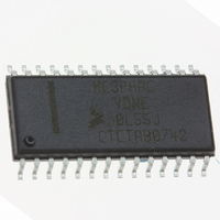
MC3PHACVDWE Freescale Semiconductor, MC3PHACVDWE Datasheet - Page 12

MC3PHACVDWE
Manufacturer Part Number
MC3PHACVDWE
Description
IC MOTOR CONTROLLER 28-SOIC
Manufacturer
Freescale Semiconductor
Datasheet
1.MC3PHACVFAE.pdf
(36 pages)
Specifications of MC3PHACVDWE
Applications
AC Motor Controller, 3 Phase
Number Of Outputs
1
Voltage - Supply
4.5 V ~ 5.5 V
Operating Temperature
-40°C ~ 105°C
Mounting Type
Surface Mount
Package / Case
28-SOIC (7.5mm Width)
Processor Series
MC3PHAC
Core
HC08
Data Bus Width
8 bit
Program Memory Type
Flash
Program Memory Size
8 KB
Data Ram Size
256 KB
Interface Type
SCI
Maximum Clock Frequency
8.2 MHz
Number Of Programmable I/os
14
Number Of Timers
2
Maximum Operating Temperature
+ 85 C
Mounting Style
SMD/SMT
Minimum Operating Temperature
- 40 C
On-chip Adc
10 bit, 4 Channel
Lead Free Status / RoHS Status
Lead free / RoHS Compliant
Current - Output
-
Voltage - Load
-
Lead Free Status / Rohs Status
Details
Available stocks
Company
Part Number
Manufacturer
Quantity
Price
Company:
Part Number:
MC3PHACVDWE
Manufacturer:
NSC
Quantity:
1 430
Features
illustrated in
voltage curve in
The MC3PHAC allows the voltage boost to be specified as a percentage of full voltage at 0 Hz, as shown
in
a voltage to the MUX_IN pin while the VBOOST_MODE pin is being driven low. Refer to the graph in
Figure 11
this way, voltage boost can be specified from 0 to 40 percent, with a scaling factor of 8 percent per volt.
In PC master software mode, the voltage boost can be specified from 0 to 100 percent and can be
changed at anytime.
By using the voltage boost value, and the specified base frequency, the MC3PHAC has all the information
required to generate a voltage profile automatically based on the generated waveform frequency. An
additional feature exists in PC master software mode whereby this voltage value can be overridden and
controlled in real time. Specifying a voltage lower than the normal volts-per-hertz profile permits a softer
torque response in certain ergonomic situations. It also allows for load power factor control and higher
operating efficiencies with high inertia loads or other loads where instantaneous changes in torque
demand are not permitted. Details of this feature are discussed in the
the
PLL Clock Generation — The OSC1 pin signal is used as a reference clock for an internal PLL clocking
circuit, which is used to drive the internal clocks of the MC3PHAC. This provides excellent protection
against noise spikes that may occur on the OSC1 pin. In a clocking circuit that does not incorporate a PLL,
a noise spike on the clock input can create a clock edge, which violates the setup times of the clocking
12
Figure
MC3PHAC.
5. In standalone mode, voltage boost is specified during the initialization phase by supplying
for the resistance value versus voltage boost.
Figure 6. AC Motor Single Phase Model Showing Parasitic Stator Impedances
Figure
Figure
6. To compensate for this voltage loss, the voltage profile is boosted over the normal
VOLTAGE BOOST
5, so that the magnetizing current remains constant over the speed range.
Figure 5. Voltage Profiling, Including Voltage Boost
(TRY TO KEEP CONSTANT)
MC3PHAC Monolithic Intelligent Motor Controller, Rev. 2
MAGNETIZING CURRENT
100%
X
PARASITICS
1
BASE FREQUENCY
R
1
X
M
TORQUE CURRENT
X
Figure 11
2
assumes a 6.8 kΩ pullup resistor. In
R
2
PC Master Software Operation with
FREQUENCY
R2 (1 –s)
s
Freescale Semiconductor


