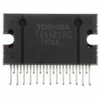
TB6581HG Toshiba, TB6581HG Datasheet - Page 11

TB6581HG
Manufacturer Part Number
TB6581HG
Description
IC BRUSHLESS MOTOR CTLR 25HZIP
Manufacturer
Toshiba
Type
3 Phase Full Wave Sine Wave PWM Brushless Motor Controllerr
Datasheet
1.TB6581HG.pdf
(15 pages)
Specifications of TB6581HG
Applications
DC Motor Controller, Brushless (BLDC), 3 Phase
Number Of Outputs
1
Current - Output
1A
Voltage - Load
50 V ~ 400 V
Voltage - Supply
13.5 V ~ 16.5 V
Operating Temperature
-30°C ~ 115°C
Mounting Type
Through Hole
Package / Case
25-HZIP
Product
Fan / Motor Controllers / Drivers
Operating Supply Voltage
15 V, 7 V
Supply Current
3 mA, 6 mA
Mounting Style
SMD/SMT
Lead Free Status / RoHS Status
Lead free / RoHS Compliant
Available stocks
Company
Part Number
Manufacturer
Quantity
Price
Company:
Part Number:
TB6581HG
Manufacturer:
Toshiba
Quantity:
10
Company:
Part Number:
TB6581HG
Manufacturer:
NORTEL
Quantity:
89
Part Number:
TB6581HG
Manufacturer:
TOSHIBA/东芝
Quantity:
20 000
External Parts
Other Precautions
short-circuiting between outputs, air contamination faults, or faults due to improper grounding, or by
short-circuiting between contiguous pins.
Vcc15 and VB may be turned on in either order. In turning off the power, take care not to cut off the VB line by
relay while the motor is spinning. Doing so may cause the IC to break down by cutting the current-producing route
for VB.
150˚C. The maximum heat is 260˚C, to be applied within 10 seconds and as far as the lead stopper.
Utmost care is necessary in the design of the output, V
In turning on the power, first supply Vcc15 and confirm its stability; then apply Vcc7 and the driving input signal.
The TB6581H/HG is sensitive to electrostatic discharge. Handle with care.
The product should be mounted by the solder-flow method. The preheating time is from 60 to 120 seconds at
Note 1: For carrier frequency and dead time, connect a 4.19 MHz ceramic resonator.
Note 2: These parts are used as a low-pass filter for noise absorption. Test to confirm noise filtering, then set the
Note 3: This part is used as a capacitor for power supply stability. Adjust the part to the application environment as
Note 4: This part is used to set the value for overcurrent detection. I
Note 5: The required bootstrap capacitance value varies according to the motor drive conditions. The voltage stress
C
C
R
10
Symbol
1
1
, C
, C
, R
X
C
C
R
R
C
C
C
C
filter time-constant.
required. When mounting, place it as close as possible to the base of the leads of this product to improve
the noise elimination.
for the capacitor is the value of V
11
1
2
2
4
5
4
5
6
7
8
9
, C
, R
, C
3
3
12
V
V
V
CC15
REG
Internal clock generation
refout
Overcurrent detection
Bootstrap capacitor
Noise absorber
Noise absorber
power supply stability
power supply stability
oscillation protection
Purpose
CC15
.
Recommended value
10 V/0.1 µF~1.0 µF
0.62 Ω ± 1% (1 W)
16 V/1.0 µF~10 µF
11
CC
10 V/1000 pF
10 V/1000 pF
10 V/1000pF
25 V/0.1 µF
25 V/2.2 µF
25 V/10 µF
, V
4.19 MHz
5.1 kΩ
10 kΩ
M
, and GND lines since the IC may be destroyed by
out (max)
= V
dc
Note
(Note 1)
(Note 2)
(Note 3)
(Note 2)
(Note 4)
(Note 3)
(Note 3)
(Note 5)
÷ R
5
(V
dc
= 0.5 V (typ.))
TB6581H/HG
2006-03-02


