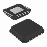
ISL6144IRZA-T Intersil, ISL6144IRZA-T Datasheet - Page 19

ISL6144IRZA-T
Manufacturer Part Number
ISL6144IRZA-T
Description
IC CTRLR MOSFET HV ORING 20-QFN
Manufacturer
Intersil
Datasheet
1.ISL6144IVZA.pdf
(29 pages)
Specifications of ISL6144IRZA-T
Applications
Telecom/Datacom Systems
Fet Type
N-Channel
Number Of Outputs
1
Internal Switch(s)
No
Delay Time - On
1ms
Delay Time - Off
250ns
Voltage - Supply
10 V ~ 75 V
Operating Temperature
-40°C ~ 105°C
Mounting Type
Surface Mount
Package / Case
20-VQFN Exposed Pad, 20-HVQFN, 20-SQFN, 20-DHVQFN
Lead Free Status / RoHS Status
Lead free / RoHS Compliant
Current - Supply
-
Available stocks
Company
Part Number
Manufacturer
Quantity
Price
Company:
Part Number:
ISL6144IRZA-T
Manufacturer:
Intersil
Quantity:
4 800
The ISL6144EVAL1Z board has V
changed if performance is found to be unacceptable with this
value. V
(short pulse) that might flow before the gate is effectively
turned off (details on how to select V
later section of this application note). The r
HS comp offset also contribute to the amplitude of the reverse
current pulse. A short event on a single feed may cause
ringing on the ground pins, the V
This ringing may cause false turn-off on the healthy feeds.
Using decoupling capacitors both at the V
help in filtering this high frequency ringing and prevent false
turn-off of parallel feeds. Figure 23 shows that the gate of
second feed V
affected when feed 1 input is shorted.
Power Supply Slow Turn-off
In many cases, a single power feed is turned off for
diagnosis, maintenance or replacement. The Input voltage
drops slowly (most probably in few ms). When voltage at V
pin starts dropping with respect to V
Regulating Amplifier starts pulling down current (I
opposite to the charge pump current. This reduces the gate
voltage gradually until the MOSFET is completely turned off.
The slow turn-off is accomplished with zero reverse current.
An internal 20µs delay filters out any false trip off due to
noise or glitches that might be present on the supply line.
The slow speed turn-off mechanism is shown in Figure 24:
FIGURE 24. SLOW SPEED TURN-OFF (C
10V/DIV
20µs/DIV
V
OUT
2A/DIV
TH(HS)
I
IN2
5V/DIV
V
GS2
G2
5ms/DIV
can affect the amplitude of the reverse current
V
OUT
(measured with respect to ground) is not
I
IN2
V
GS2
V
IN1
ZOOMED IN VIEW
= V
IN2
19
= 48V
IN
TH(HS)
, and on the V
TH(HS)
OUT
GSTOT
of 55mV. It can be
DS(ON)
IN
pin. The Hysteretic
V
IN2
is included in a
and V
10V/DIV
V
= 8.4nF + 33nF)
IN2
OUT
and internal
OUT
PDL
pins.
)
pins
IN
ISL6144
Input Voltage is falling at a slow rate (Figure 24, top scope
shot shows a 20ms fall time for the input voltage).
V
48V. It drops by a value equivalent to the increase in the
portion of the load current passing through the remaining
feed multiplied by the MOSFET’s r
At the beginning of the slow turn-off, the gate drive Voltage
V
ORing MOSFET using a differential probe) starts to drop at a
slower rate. This is attributed to the effect of the 20µs
filtering-delay. Afterwards a stronger pull down current starts
and finally the high-speed turn-off completes the gate turn-
off. Current through the turned off feed is also shown to be
positive and the turn-off is complete with no reverse current.
Figure 25 shows the same slow turn-off for a 12V input
voltage case.
FIGURE 25. SLOW SPEED TURN-OFF (C
OUT
GS1
20µs/DIV
(measured between the Gate and Source of the
(Common Bus) remains almost unchanged at around
5ms/DIV
V
IN1
V
5V/DIV
GS1 (DIFF PROBE)
= V
IN2
= 12V
ZOOMED IN VIEW
DS(ON)
GSTOT
.
= 8.4nF + 33nF)
January 6, 2011
2V/DIV
2A/DIV
V
2V/DIV
V
I
OUT
IN1
IN1
FN9131.6


