L6563HTR STMicroelectronics, L6563HTR Datasheet - Page 34

L6563HTR
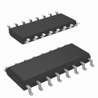
Manufacturer Part Number
L6563HTR
Description
IC PFC CTRLR TRANSITION 16SOIC
Manufacturer
STMicroelectronics
Specifications of L6563HTR
Mode
Discontinuous (Transition)
Current - Startup
90µA
Voltage - Supply
10.3 V ~ 22.5 V
Operating Temperature
-25°C ~ 125°C
Mounting Type
Surface Mount
Package / Case
16-SOIC (3.9mm Width)
For Use With
497-9082 - EVAL BOARD L6563 (200W)497-8850 - BOARD EVAL FOR L6563/STW55NM60N497-8834 - BOARD DEMO FOR L6563/LL6566A
Lead Free Status / RoHS Status
Lead free / RoHS Compliant
Frequency - Switching
-
Lead Free Status / Rohs Status
Lead free / RoHS Compliant
Other names
497-9075-2
Available stocks
Company
Part Number
Manufacturer
Quantity
Price
Company:
Part Number:
L6563HTR
Manufacturer:
ST
Quantity:
3 100
Company:
Part Number:
L6563HTR
Manufacturer:
TI
Quantity:
10 000
Part Number:
L6563HTR
Manufacturer:
ST
Quantity:
20 000
Application information
34/48
Figure 49. Interface circuits for actual power-up sequencing (master PFC)
Another possible use of the RUN and PWM_STOP pins (again, in systems where the PFC
stage is the master) is the brownout protection, thanks to the hysteresis provided.
The brownout protection is basically a not-latched device shutdown function that is activated
when a condition of mains undervoltage is detected. This condition may cause overheating
of the primary power section due to an excess of RMS current. Brownout can also cause the
PFC pre-regulator to work open loop and this could be dangerous to the PFC stage itself
and the downstream converter, should the input voltage return abruptly to its rated value.
Another problem is the spurious restarts that may occur during converter power down and
that cause the output voltage of the converter not to decay to zero monotonically. For these
reasons it is usually preferable to shutdown the unit in case of brownout.
IC shutdown upon brownout can be easily realized as shown in
the left is of general use, that one on the right can be used if the bias levels of the multiplier
and the R
specified holdup time respectively. In this latest case, an additional resistor voltage divider
and one capacitor are not needed.
In table 1 it is possible to find a summary of all of the above mentioned working conditions
that cause the device to stop operating.
Figure 50. Brownout protection (master PFC)
FF
·C
FF
time constant are compatible with the specified brownout level and with the
RUN
RUN
12
12
Doc ID 16047 Rev 2
L6563H
L6563H
Figure 50
L6563H
L6563H
. The scheme on
RUN
RUN
12
12
L6563H


