XC8101AA01MR Torex Semiconductor Ltd, XC8101AA01MR Datasheet
XC8101AA01MR
Specifications of XC8101AA01MR


Related parts for XC8101AA01MR


XC8101AA01MR Summary of contents
Page 1
XC8101 Series High Side Load Switch with Low Supply Current ■ GENERAL DESCRIPTION The XC8101 series is a low supply current load switch IC with ON/OFF control and output current protection which integrates P-channel MOSFET. The XC8101 is suited for ...
Page 2
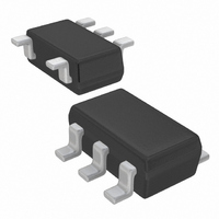
XC8101 Series ■PIN CONFIGURATION USP-4 (BOTTOM VIEW) *The heat dissipation pad of the USP-4 package is recommended to solder as shown in the recommended mount pattern and metal mask pattern for mounting strength. The heat dissipation pad should be electrically ...
Page 3
DIAGRAM ●XC8101AA Series * Diodes inside the circuit are an ESD protection diode and a parasitic diode. ■ABSOLUTE MAXIMUM RATINGS PARAMETER Input Voltage Output Current Output Voltage CE Input Voltage USP-4 SOT-25 Power Dissipation SSOT-24 Operating Temperature Range Storage ...
Page 4
XC8101 Series ■ELECTRICAL CHARACTERISTICS ●XC8101AA Series PARAMETER SYMBOL Input Voltage Resistance R ON (SSOT-24 / USP-4) On Resistance R ON (SOT-25) Supply Current I DD Stand-by Current I STBY Switch Leakage Current I LEAK Current Limit I ...
Page 5
CIRCUITS Circuit ① Circuit ② Circuit ③ XC8101 Series 5/37 ...
Page 6
XC8101 Series ■TEST CIRCUITS (Continued) Circuit ④ Circuit ⑤ The measurement point of wave form 6/37 The measurement point of wave form ...
Page 7
EXPLANATION <CE Pin> The XC8101 enables an output P-channel MOSFET switch and the IC internal circuitry to turn off by the signal to the CE pin. In the shutdown mode, the V pin will be pulled down to the ...
Page 8
XC8101 Series ■TYPICAL PERFORMANCE CHARACTERISTICS (1) ON Resistance vs. Input Voltage XC8101A A 01N / XC8101A A01G 2.0 1.6 1.2 0.8 0.4 0.0 1.5 2.0 2.5 3.0 3.5 4.0 4.5 Input Voltage: VIN (V ) (2) ON Resistance vs. Ambient ...
Page 9
PERFORMANCE CHARACTERISTICS (Continued) (5) Output Voltage vs. Output Current XC8101A A 01N / XC8101A A 01G V IN=CE=1.8V CIN=None, CL=None 5.0 4.0 3.0 2.0 1.0 0 100 150 200 250 300 350 Output Current: IOUT (mA ) ...
Page 10
XC8101 Series ■TYPICAL PERFORMANCE CHARACTERISTICS (Continued) (5) Output Voltage vs. Output Current (Continued) XC8101AA 01M V IN=CE=4.0V CIN=None, CL=None 5.0 4.0 3.0 2.0 1.0 0 100 150 200 250 300 Output Current: IOUT (mA ) (6) CE Threshold ...
Page 11
PERFORMANCE CHARACTERISTICS (Continued) (8) Output Turn-on Time with CE (Continued) XC8101AA 01 VIN=4.0V CE=0.3V → 1.2V tr=tf =5 μ IOUT=50mA CIN=None , CL=None 1.5 1.0 0.5 0.0 CE Input Voltage -0.5 Output Voltage -1.0 -1.5 -2.0 Time: ...
Page 12
XC8101 Series ■TYPICAL PERFORMANCE CHARACTERISTICS (Continued) (8) Output Turn-on Time with CE (Continued) XC8101A A 01 VIN=1.8V CE=0.3V → 1.2V tr=tf=5 μ IOUT=50mA CIN=None , CL=0.47 μ F 1.5 1.0 CE Input V oltage 0.5 0.0 -0.5 -1.0 ...
Page 13
PERFORMANCE CHARACTERISTICS (Continued) (8) Output Turn-on Time with CE (Continued) XC8101AA 01 VIN=4.0V CE=0.3V → 1.2V tr=tf=5 μ IOUT=50mA CIN=None , CL=1 μ F 1.5 1.0 CE Input Voltage 0.5 0.0 -0.5 -1.0 Output Voltage -1.5 -2.0 ...
Page 14
XC8101 Series ■TYPICAL PERFORMANCE CHARACTERISTICS (Continued) (8) Output Turn-on Time with CE (Continued) XC8101A A 01 VIN=1.8V CE=0.3V → 1.2V tr=tf=5 μ IOUT=50mA CIN=0.1 μ CL=0.47 μ F 1.5 1.0 CE Input V oltage 0.5 0.0 ...
Page 15
PERFORMANCE CHARACTERISTICS (Continued) (8) Output Turn-on Time with CE (Continued) XC8101AA 01 VIN=4.0V CE=0.3V → 1.2V tr=tf =5 μ IOUT=50mA CIN=0.1 μ CL=1 μ F 1.5 1.0 CE Input Voltage 0.5 0.0 -0.5 -1.0 Output ...
Page 16
XC8101 Series ■TYPICAL PERFORMANCE CHARACTERISTICS (Continued) (8) Output Turn-on Time with CE (Continued) XC8101A A 01 VIN=1.8V CE=0.3V → 1.2V tr=tf =5 μ IOUT=50mA CIN=0.22 μ CL=0.47 μ F 1.5 1.0 CE Input V oltage 0.5 ...
Page 17
PERFORMANCE CHARACTERISTICS (Continued) (8) Output Turn-on Time with CE (Continued) XC8101AA 01 VIN=4.0V CE=0.3V → 1.2V tr=tf =5 μ IOUT=50mA CIN=0.22 μ CL=1 μ F 1.5 1.0 CE Input Voltage 0.5 0.0 -0.5 Output Voltage ...
Page 18
XC8101 Series ■TYPICAL PERFORMANCE CHARACTERISTICS (Continued) (8) Output Turn-on Time with CE (Continued) XC8101A A 01 VIN=1.8V CE=0.3V → 1.2V tr=tf =5 μ IOUT=50mA CIN=0.47 μ CL=0.47 μ F 1.5 1.0 CE Input V oltage 0.5 ...
Page 19
PERFORMANCE CHARACTERISTICS (Continued) (8) Output Turn-on Time with CE (Continued) XC8101AA 01 VIN=4.0V CE=0.3V → 1.2V tr=tf =5 μ IOUT=50mA CIN=0.47 μ CL=1 μ F 1.5 1.0 CE Input Voltage 0.5 0.0 -0.5 Output V ...
Page 20
XC8101 Series ■TYPICAL PERFORMANCE CHARACTERISTICS (Continued) (8) Output Turn-on Time with CE (Continued) XC8101A A 01 VIN=1.8V CE=0.3V → 1.2V tr=tf =5 μ IOUT=50mA CIN=1 μ CL=0.47 μ F 1.5 1.0 CE Input V oltage 0.5 ...
Page 21
PERFORMANCE CHARACTERISTICS (Continued) (8) Output Turn-on Time with CE (Continued) XC8101AA 01 VIN=4.0V CE=0.3V → 1.2V tr=tf =5 μ IOUT=50mA CIN=1 μ CL=1 μ F 1.5 1.0 CE Input Voltage 0.5 0.0 -0.5 -1.0 Output ...
Page 22
XC8101 Series ■TYPICAL PERFORMANCE CHARACTERISTICS (Continued) (9) Output Turn-off Time with CE (Continued) XC8101A A01 VIN=1.8V CE=1.2V → 0.3V tr=tf =5 μ IOUT=50mA CIN=None , CL=0.1 μ F 1.5 1.0 CE Input Voltage 0.5 0.0 -0.5 Output V ...
Page 23
PERFORMANCE CHARACTERISTICS (Continued) (9) Output Turn-off Time with CE (Continued) XC8101A A01 VIN=4.0V CE=1.2V → 0.3V tr=tf =5 μ IOUT=50mA CIN=None , CL=0.47 μ F 1.5 1.0 CE Input Voltage 0.5 0.0 -0.5 Output Voltage -1.0 -1.5 ...
Page 24
XC8101 Series ■TYPICAL PERFORMANCE CHARACTERISTICS (Continued) (9) Output Turn-off Time with CE (Continued) XC8101A A01 VIN=1.8V CE=1.2V → 0.3V tr=tf =5 μ IOUT=50mA CIN=0.1 μ CL=0.1 μ F 1.5 1.0 CE Input Voltage 0.5 0.0 Output ...
Page 25
PERFORMANCE CHARACTERISTICS (Continued) (9) Output Turn-off Time with CE (Continued) XC8101A A01 VIN=4.0V CE=1.2V → 0.3V tr=tf =5 μ IOUT=50mA CIN=0.1 μ CL=0.47 μ F 1.5 1.0 CE Input Voltage 0.5 0.0 -0.5 Output Voltage ...
Page 26
XC8101 Series ■TYPICAL PERFORMANCE CHARACTERISTICS (Continued) (9) Output Turn-off Time with CE (Continued) XC8101A A01 VIN=1.8V CE=1.2V → 0.3V tr=tf =5 μ IOUT=50mA CIN=0.22 μ CL=0.1 μ F 1.5 1.0 CE Input Voltage 0.5 0.0 -0.5 ...
Page 27
PERFORMANCE CHARACTERISTICS (Continued) (9) Output Turn-off Time with CE (Continued) XC8101A A01 VIN=4.0V CE=1.2V → 0.3V tr=tf =5 μ IOUT=50mA CIN=0.22 μ CL=0.47 μ F 1.5 1.0 CE Input Voltage 0.5 0.0 -0.5 Output Voltage ...
Page 28
XC8101 Series ■TYPICAL PERFORMANCE CHARACTERISTICS (Continued) (9) Output Turn-off Time with CE (Continued) XC8101A A01 VIN=1.8V CE=1.2V → 0.3V tr=tf =5 μ IOUT=50mA CIN=0.47 μ CL=0.1 μ F 1.5 1.0 CE Input Voltage 0.5 0.0 -0.5 ...
Page 29
PERFORMANCE CHARACTERISTICS (Continued) (9) Output Turn-off Time with CE (Continued) XC8101A A01 VIN=4.0V CE=1.2V → 0.3V tr=tf =5 μ IOUT=50mA CIN=0.47 μ CL=0.47 μ F 1.5 1.0 CE Input Voltage 0.5 0.0 -0.5 Output Voltage ...
Page 30
XC8101 Series ■TYPICAL PERFORMANCE CHARACTERISTICS (Continued) (9) Output Turn-off Time with CE (Continued) XC8101A A01 VIN=1.8V CE=1.2V → 0.3V tr=tf =5 μ IOUT=50mA CIN=1 μ CL=0.1 μ F 1.5 1.0 CE Input Voltage 0.5 0.0 -0.5 ...
Page 31
PERFORMANCE CHARACTERISTICS (Continued) (9) Output Turn-off Time with CE (Continued) XC8101A A01 VIN=4.0V CE=1.2V → 0.3V tr=tf =5 μ IOUT=50mA CIN=1 μ CL=0.47 μ F 1.5 1.0 CE Input Voltage 0.5 0.0 -0.5 Output V ...
Page 32
XC8101 Series ■PACKAGING INFORMATION ●SOT-25 ●USP-4 32/37 ●SSOT-24 Unit : mm Unit : mm Unit : mm ...
Page 33
INFORMATION (Continued) ● SOT-25 Power Dissipation Power dissipation data for the SOT-25 is shown in this page. The value of power dissipation varies with the mount board conditions. Please use this data as one of reference data taken in ...
Page 34
XC8101 Series ■PACKAGING INFORMATION (Continued) ● SSOT-24 Power Dissipation Power dissipation data for the SSOT-24 is shown in this page. The value of power dissipation varies with the mount board conditions. Please use this data as one of reference data ...
Page 35
INFORMATION (Continued) ● USP-4 Power Dissipation Power dissipation data for the USP-4 is shown in this page. The value of power dissipation varies with the mount board conditions. Please use this data as one of reference data taken in ...
Page 36
XC8101 Series ■MARKING RULE ●SOT-25、USP-4 ① represents product series MARK PRODUCT SERIES U XC8101****** ② represents CE pin logic MARK PRODUCT SERIES F XC8101A***** ③ represents C Discharge Function L MARK PRODUCT SERIES C XC8101AA**** ④⑤ represents production lot number ...
Page 37
... Should you wish to use the products under conditions exceeding the specifications, please consult us or our representatives assume no responsibility for damage or loss due to abnormal use. 7. All rights reserved. No part of this datasheet may be copied or reproduced without the prior permission of TOREX SEMICONDUCTOR LTD. XC8101 Series 37/37 ...