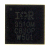
IR3510MTRPBF International Rectifier, IR3510MTRPBF Datasheet - Page 28

IR3510MTRPBF
Manufacturer Part Number
IR3510MTRPBF
Description
IC XPHASE CONTROL 32-MLPQ
Manufacturer
International Rectifier
Series
XPhase™r
Datasheet
1.IR3510MTRPBF.pdf
(36 pages)
Specifications of IR3510MTRPBF
Applications
Processor
Mounting Type
Surface Mount
Package / Case
32-MLPQ
Package
32-Lead MLPQ
Circuit
X-Phase Control IC
Pbf
PbF Option Available
Lead Free Status / RoHS Status
Lead free / RoHS Compliant
Current - Supply
-
Voltage - Supply
-
Operating Temperature
-
Other names
IR3510MTRPBFTR
Available stocks
Company
Part Number
Manufacturer
Quantity
Price
Part Number:
IR3510MTRPBF
Manufacturer:
IR
Quantity:
20 000
VCC,CX and VBIAS Caps
Both VCC and VBIAS require a 0.1 uF 16V 0603 cap. For Charge Pump output cap CX, a 0.1uF 50V 0603 cap is
needed since the charge pump voltage can be up to 27V.
Oscillator Resistor Rosc
The oscillator of IR3510 generates a triangle waveform to synchronize the phase ICs, and the switching frequency
of the each phase equals the oscillator frequency, which is set by the external resistor R
in Fig. 16.
Soft Start Capacitor C
The soft start capacitor C
voltage after the input FET, and the converter output voltage. An internal 70uA current source charges the soft-
start cap until it reaches the final charge-up voltage, which is typical 3.8V. It sets the input voltage ramp-up time,
the output delay time, the output voltage ramp-up time and the VRRDY delay time.
The input voltage ramp-up time is determined by the input soft-start regulator gain Kss, which is typical 4.5, Vin
and the input voltage applied before the input FET. Assume the input FET gate charge is small enough, so the
gate voltage can follow the soft-start cap voltage,
If the input FET has large gate charge or more than one input FETs are paralleled, the gate charge current may
not be large enough to keep the voltage following the soft-start cap voltage, resulting in longer ramp-up time.
There is a delay time added in the soft-start of the converter output. The voltage error amplifier output is held
LOW until the soft-start cap reaches 1.35v, resulting in the delay time.
After the soft-start cap voltage moves above 1.35V, the voltage error amplifier is released and the feedback
voltage VFB follows the soft-start cap voltage until it reaches the VSET voltage. Assuming the final VFB is less
than the soft-start charge-up voltage, the converter output voltage ramp-up time is,
1000
950
900
850
800
750
700
650
600
550
500
450
400
350
300
250
200
150
10
Page 28 of 36
15
Fig. 16 Switching frequency Vs. Rosc
20
25
30
Oscillator Frequency versus ROSC
35
40
SS
45
SS
ROSC (K Ohms)
50
programs the soft start time for both the voltage regulator input voltage, which is the
55
60
Tir
Tod
65
=
70
=
I
75
C
C
CHG
SS
SS
80
I
*
CHG
*
*
85
Vin
. 1
Kss
IR Confidential
90
35
95 100
=
=
70
C
70
SS
*
C
*
10
SS
*
10
. 1
−
*
6
35
−
12
6
*
4
125
115
105
95
85
75
65
55
45
35
25
15
5 .
5
10
Fig. 17 Irosc Current Vs. Rosc
15
20
25
30
35
Irosc Currents vs ROSC
40
45
ROSC (K Ohm)
50
OSC
55
May 18, 2009
60
according to the curve
65
70
IR3510
75
80
85
90
95 100


