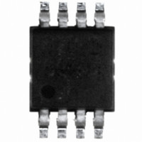
DS620U+ Maxim Integrated Products, DS620U+ Datasheet - Page 11

DS620U+
Manufacturer Part Number
DS620U+
Description
IC THERMOMETER/STAT DIG 8MSOP
Manufacturer
Maxim Integrated Products
Datasheet
1.DS620U.pdf
(15 pages)
Specifications of DS620U+
Function
Thermometer, Thermostat
Topology
ADC (Sigma Delta), Register Bank
Sensor Type
Internal
Sensing Temperature
-55°C ~ 125°C
Output Type
I²C™/SMBus™
Output Alarm
No
Output Fan
No
Voltage - Supply
1.7 V ~ 3.5 V
Operating Temperature
-55°C ~ 125°C
Mounting Type
Surface Mount
Package / Case
8-MSOP Exposed Pad, 8-HMSOP, 8-eMSOP
Temperature Threshold
Programmable
Full Temp Accuracy
+/- 0.5 C
Digital Output - Bus Interface
2-Wire, SMBus
Digital Output - Number Of Bits
10 bit to 13 bit
Supply Voltage (max)
3.5 V
Supply Voltage (min)
1.7 V
Maximum Operating Temperature
+ 125 C
Minimum Operating Temperature
- 55 C
Supply Current
800 uA
Lead Free Status / RoHS Status
Lead free / RoHS Compliant
is acting as a receiver, it uses a NACK instead of an ACK after the last data byte to indicate that it is finished
receiving data. The master indicates a NACK by leaving the SDA line high during the ACK clock cycle.
Slave Address: Every slave device on the bus has a unique 7-bit address that allows the master to access that
device. The DS620’s 7-bit bus address is 1 0 0 1 A
corresponding input pins. The three address pins allow up to eight DS620s to be multidropped on the same bus.
Control Byte: The control byte is transmitted by the master and consists of the 7-bit slave address plus a
read/write (R/W ¯ ¯) bit (see Figure 7). If the master is going to read data from the slave device then R/W ¯ ¯ = 1, and if
the master is going to write data to the slave device then R/W ¯ ¯ = 0.
Address Byte: The address byte is used by the master to tell the DS620 which address location in the memory
map in Table 4 is going to be accessed during communication or which command should be performed. See
Command Set section.
Figure 6. START, STOP, AND ACK SIGNALS
Figure 7. Control Byte
GENERAL 2-WIRE INFORMATION
INITIATING 2-WIRE COMMUNICATION
To initiate 2-wire communication, the master generates a START followed by a control byte containing the DS620
slave address. The R/W bit of the control byte must be a 0 (write) since the master next writes a command byte or
an address byte. The DS620 responds with an ACK after receiving the control byte. This must be followed by a
command byte from the master which indicates what type of command operation is to be performed, or an address
byte when the master intends to write to or read from the DS620. The DS620 again responds with an ACK after
receiving the command or address byte. The master can then issue a STOP to signal the end of the
communication sequence, or continue writing to the address memory. See the Command Set section for details on
All data is transmitted MSb first over the 2-wire bus.
One bit of data is transmitted on the 2-wire bus each SCL period.
A pullup resistor is required on the SDA line and, when the bus is idle, both SDA and SCL must remain in a logic-
high state.
All bus communication must be initiated with a START condition and terminated with a STOP condition. During a
START or STOP is the only time SDA is allowed to change states while SCL is high. At all other times, changes
on the SDA line can only occur when SCL is low: SDA must remain stable when SCL is high.
After every 8-bit (1-byte) transfer, the receiving device must answer with an ACK (or NACK), which takes one
SCL period. Therefore, nine clocks are required for every one-byte data transfer.
bit 7
SDA
SCL
1
Condition
START
bit 6
0
bit 5
0
bit 4
1
11 of 15
2
…
…
A
bit 3
1
A
A
2
0
ACK (or NACK)
From Receiver
, where A
bit 2
A
1
2
, A
1
bit 1
, and A
A
Condition
0
STOP
0
R/
bit 0
are user-selectable via the
W ¯ ¯


